Example: Configuring CFD
Network configuration
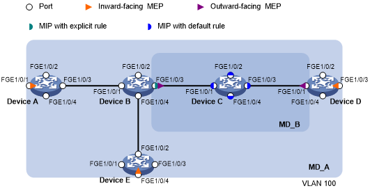
As shown in Figure 5:
The network comprises five devices and is divided into two MDs: MD_A (level 5) and MD_B (level 3). All ports belong to VLAN 100, and the MAs in the two MDs all serve VLAN 100. Assume that the MAC addresses of Device A through Device E are 0010-FC01-6511, 0010-FC02-6512, 0010-FC03-6513, 0010-FC04-6514, and 0010-FC05-6515, respectively.
MD_A has three edge ports: FortyGigE 1/0/1 on Device A, FortyGigE 1/0/3 on Device D, and FortyGigE 1/0/4 on Device E. They are all inward-facing MEPs. MD_B has two edge ports: on Device B and FortyGigE 1/0/1 on Device D. They are both outward-facing MEPs.
In MD_A, Device B is designed to have MIPs when its port is configured with low level MEPs. Port FortyGigE 1/0/3 is configured with MEPs of MD_B, and the MIPs of MD_A can be configured on this port. You must configure the MIP generation rule of MD_A as explicit.
The MIPs of MD_B are designed on Device C, and are configured on all ports. You must configure the MIP generation rule as default.
Configure CC to monitor the connectivity among all the MEPs in MD_A and MD_B. Configure LB to locate link faults, and use the AIS and EAIS functions to suppress the error alarms that are reported.
After the status information of the entire network is obtained, use LT, LM, one-way DM, two-way DM, and TST to detect link faults.
Figure 5: Network diagram
Procedure
![[IMPORTANT: ]](images/important.png) | IMPORTANT: By default, interfaces on the device are disabled (in ADM or Administratively Down state). To have an interface operate, you must use the undo shutdown command to enable that interface. | |
Configure a VLAN and assign ports to it:
On each device shown in Figure 5, create VLAN 100 and assign ports FortyGigE 1/0/1 through FortyGigE 1/0/4 to VLAN 100.
Enable CFD:
# Enable CFD on Device A.
<DeviceA> system-view
[DeviceA] cfd enable
# Configure Device B through Device E in the same way Device A is configured. (Details not shown.)
Configure service instances:
# Create MD_A (level 5) on Device A, and create service instance 1 (in which the MA is identified by a VLAN and serves VLAN 100).
[DeviceA] cfd md MD_A level 5
[DeviceA] cfd service-instance 1 ma-id vlan-based md MD_A vlan 100
# Configure Device E in the same way Device A is configured. (Details not shown.)
# Create MD_A (level 5) on Device B, and create service instance 1 (in which the MA is identified by a VLAN and serves VLAN 100).
[DeviceB] cfd md MD_A level 5
[DeviceB] cfd service-instance 1 ma-id vlan-based md MD_A vlan 100
# Create MD_B (level 3), and create service instance 2 (in which the MA is identified by a VLAN and serves VLAN 100).
[DeviceB] cfd md MD_B level 3
[DeviceB] cfd service-instance 2 ma-id vlan-based md MD_B vlan 100
# Configure Device D in the same way Device B is configured. (Details not shown.)
# Create MD_B (level 3) on Device C, and create service instance 2 (in which the MA is identified by a VLAN and serves VLAN 100).
[DeviceC] cfd md MD_B level 3
[DeviceC] cfd service-instance 2 ma-id vlan-based md MD_B vlan 100
Configure MEPs:
# On Device A, configure a MEP list in service instance 1, and create inward-facing MEP 1001 in service instance 1 on FortyGigE 1/0/1.
[DeviceA] cfd meplist 1001 4002 5001 service-instance 1
[DeviceA] interface fortygige 1/0/1
[DeviceA-FortyGigE1/0/1] cfd mep 1001 service-instance 1 inbound
[DeviceA-FortyGigE1/0/1] quit
# On Device B, configure a MEP list in service instances 1 and 2.
[DeviceB] cfd meplist 1001 4002 5001 service-instance 1
[DeviceB] cfd meplist 2001 4001 service-instance 2
# Create outward-facing MEP 2001 in service instance 2 on FortyGigE 1/0/3.
[DeviceB] interface fortygige 1/0/3
[DeviceB-] cfd mep 2001 service-instance 2 outbound
[DeviceB-FortyGigE1/0/3] quit
# On Device D, configure a MEP list in service instances 1 and 2.
[DeviceD] cfd meplist 1001 4002 5001 service-instance 1
[DeviceD] cfd meplist 2001 4001 service-instance 2
# Create outward-facing MEP 4001 in service instance 2 on FortyGigE 1/0/1.
[DeviceD] interface
[DeviceD-FortyGigE1/0/1] cfd mep 4001 service-instance 2 outbound
[DeviceD-FortyGigE1/0/1] quit
# Create inward-facing MEP 4002 in service instance 1 on FortyGigE 1/0/3.
[DeviceD] interface fortygige 1/0/3
[DeviceD-FortyGigE1/0/3] cfd mep 4002 service-instance 1 inbound
[DeviceD-FortyGigE1/0/3] quit
# On Device E, configure a MEP list in service instance 1.
[DeviceE] cfd meplist 1001 4002 5001 service-instance 1
# Create inward-facing MEP 5001 in service instance 1 on FortyGigE 1/0/4.
[DeviceE] interface fortygige 1/0/4
[DeviceE-FortyGigE1/0/4] cfd mep 5001 service-instance 1 inbound
[DeviceE-FortyGigE1/0/4] quit
Configure MIPs:
# Configure the MIP generation rule in service instance 1 on Device B as explicit.
[DeviceB] cfd mip-rule explicit service-instance 1
# Configure the MIP generation rule in service instance 2 on Device C as default.
[DeviceC] cfd mip-rule default service-instance 2
Configure CC:
# On Device A, enable the sending of CCM frames for MEP 1001 in service instance 1 on .
[DeviceA] interface fortygige 1/0/1
[DeviceA-FortyGigE1/0/1] cfd cc service-instance 1 mep 1001 enable
[DeviceA-FortyGigE1/0/1] quit
# On Device B, enable the sending of CCM frames for MEP 2001 in service instance 2 on FortyGigE 1/0/3.
[DeviceB] interface fortygige 1/0/3
[DeviceB-FortyGigE1/0/3] cfd cc service-instance 2 mep 2001 enable
[DeviceB-FortyGigE1/0/3] quit
# On Device D, enable the sending of CCM frames for MEP 4001 in service instance 2 on FortyGigE 1/0/1.
[DeviceD] interface fortygige 1/0/1
[DeviceD-] cfd cc service-instance 2 mep 4001 enable
[DeviceD-FortyGigE1/0/1] quit
# Enable the sending of CCM frames for MEP 4002 in service instance 1 on FortyGigE 1/0/3.
[DeviceD] interface fortygige 1/0/3
[DeviceD-FortyGigE1/0/3] cfd cc service-instance 1 mep 4002 enable
[DeviceD-FortyGigE1/0/3] quit
# On Device E, enable the sending of CCM frames for MEP 5001 in service instance 1 on FortyGigE 1/0/4.
[DeviceE] interface fortygige 1/0/4
[DeviceE-FortyGigE1/0/4] cfd cc service-instance 1 mep 5001 enable
[DeviceE-FortyGigE1/0/4] quit
Configure AIS:
# Enable AIS on Device B. Configure the AIS frame transmission level as 5 and AIS frame transmission interval as 1 second in service instance 2.
[DeviceB] cfd ais enable
[DeviceB] cfd ais level 5 service-instance 2
[DeviceB] cfd ais period 1 service-instance 2
Configure EAIS:
# Enable port status-AIS collaboration on Device B.
[DeviceB] cfd ais-track link-status global
# On FortyGigE 1/0/3 of Device B, configure the EAIS frame transmission level as 5 and the EAIS frame transmission interval as 60 seconds. Specify the VLANs where the EAIS frames can be transmitted as VLAN 100.
[DeviceB] interface fortygige 1/0/3
[DeviceB-] cfd ais-track link-status level 5
[DeviceB-FortyGigE1/0/3] cfd ais-track link-status period 60
[DeviceB-FortyGigE1/0/3] cfd ais-track link-status vlan 100
[DeviceB-FortyGigE1/0/3] quit
Verifying the configuration
Verify the LB function when the CC function detects a link fault:
# Enable LB on Device A to check the status of the link between MEP 1001 and MEP 5001 in service instance 1.
[DeviceA] cfd loopback service-instance 1 mep 1001 target-mep 5001
Loopback to MEP 5001 with the sequence number start from 1001-43404:
Reply from 0010-fc05-6515: sequence number=1001-43404 time=5ms
Reply from 0010-fc05-6515: sequence number=1001-43405 time=5ms
Reply from 0010-fc05-6515: sequence number=1001-43406 time=5ms
Reply from 0010-fc05-6515: sequence number=1001-43407 time=5ms
Reply from 0010-fc05-6515: sequence number=1001-43408 time=5ms
Sent: 5        Received: 5        Lost: 0
Verify the LT function after the CC function obtains the status information of the entire network:
# Identify the path between MEP 1001 and MEP 5001 in service instance 1 on Device A.
[DeviceA] cfd linktrace service-instance 1 mep 1001 target-mep 5001
Linktrace to MEP 5001 with the sequence number 1001-43462:
MAC address               TTL     Last MAC         Relay action
0010-fc05-6515            63      0010-fc02-6512   Hit
Verify the LM function after the CC function obtains the status information of the entire network:
# Test the frame loss from MEP 1001 to MEP 4002 in service instance 1 on Device A.
[DeviceA] cfd slm service-instance 1 mep 1001 target-mep 4002
Reply from 0010-fc04-6514
Far-end frame loss: 10    Near-end frame loss: 20
Reply from 0010-fc04-6514
Far-end frame loss: 40    Near-end frame loss: 40
Reply from 0010-fc04-6514
Far-end frame loss: 0     Near-end frame loss: 10
Reply from 0010-fc04-6514
Far-end frame loss: 30    Near-end frame loss: 30

Average
Far-end frame loss: 20    Near-end frame loss: 25
Far-end frame loss rate: 25.00%    Near-end frame loss rate: 32.00%
Send LMMs: 5        Received: 5        Lost: 0
Verify the one-way DM function after the CC function obtains the status information of the entire network:
# Test the one-way frame delay from MEP 1001 to MEP 4002 in service instance 1 on Device A.
[DeviceA] cfd dm one-way service-instance 1 mep 1001 target-mep 4002
5 1DMs have been sent. Please check the result on the remote device.
# Display the one-way DM result on MEP 4002 in service instance 1 on Device D.
[DeviceD] display cfd dm one-way history service-instance 1 mep 4002
Service instance: 1
MEP ID: 4002
Sent 1DM total number: 0
Received 1DM total number: 5
Frame delay: 10ms 9ms 11ms 5ms 5ms
Delay average: 8ms
Delay variation: 5ms 4ms 6ms 0ms 0ms
Variation average: 3ms
Verify the two-way DM function after the CC function obtains the status information of the entire network:
# Test the two-way frame delay from MEP 1001 to MEP 4002 in service instance 1 on Device A.
[DeviceA] cfd dm two-way service-instance 1 mep 1001 target-mep 4002
Frame delay:
Reply from 0010-fc04-6514: 2406us
Reply from 0010-fc04-6514: 2215us
Reply from 0010-fc04-6514: 2112us
Reply from 0010-fc04-6514: 1812us
Reply from 0010-fc04-6514: 2249us
Average: 2158us
Sent DMMs: 5        Received: 5        Lost: 0

Frame delay variation: 191us 103us 300us 437us
Average: 257us
Verify the TST function after the CC function obtains the status information of the entire network:
# Test the bit errors on the link from MEP 1001 to MEP 4002 in service instance 1 on Device A.
[DeviceA] cfd tst service-instance 1 mep 1001 target-mep 4002
5 TSTs have been sent. Please check the result on the remote device.
# Display the TST result on MEP 4002 in service instance 1 on Device D.
[DeviceD] display cfd tst service-instance 1 mep 4002
Service instance: 1
MEP ID: 4002
Sent TST total number: 0
Received TST total number: 5
Received from 0010-fc01-6511, Bit True,  sequence number 0
Received from 0010-fc01-6511, Bit True,  sequence number 1
Received from 0010-fc01-6511, Bit True,  sequence number 2
Received from 0010-fc01-6511, Bit True,  sequence number 3
Received from 0010-fc01-6511, Bit True,  sequence number 4