Packet type-based IPv6 interface PBR configuration example
Network requirements
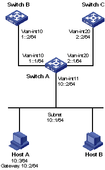
As shown in Figure 87, configure IPv6 PBR on Switch A to forward all TCP packets received on VLAN-interface 11 to the next hop 1::2. Switch A forwards other IPv6 packets according to the routing table.
Figure 87: Network diagram
Configuration procedure
Configure Switch A:
# Create VLAN 10 and VLAN 20.
<SwitchA> system-view
[SwitchA] vlan 10
[SwitchA-vlan10] quit
[SwitchA] vlan 20
[SwitchA-vlan20] quit
# Configure RIPng.
[SwitchA] ripng 1
[SwitchA-ripng-1] quit
[SwitchA] interface vlan-interface 10
[SwitchA-Vlan-interface10] ipv6 address 1::1 64
[SwitchA-Vlan-interface10] ripng 1 enable
[SwitchA-Vlan-interface10] quit
[SwitchA] interface vlan-interface 20
[SwitchA-Vlan-interface20] ipv6 address 2::1 64
[SwitchA-Vlan-interface20] ripng 1 enable
[SwitchA-Vlan-interface20] quit
# Configure ACL 3001 to match TCP packets.
[SwitchA] acl ipv6 number 3001
[SwitchA-acl6-adv-3001] rule permit tcp
[SwitchA-acl6-adv-3001] quit
# Configure Node 5 for policy aaa to forward TCP packets to next hop 1::2.
[SwitchA] ipv6 policy-based-route aaa permit node 5
[SwitchA-pbr6-aaa-5] if-match acl 3001
[SwitchA-pbr6-aaa-5] apply next-hop 1::2
[SwitchA-pbr6-aaa-5] quit
# Configure IPv6 interface PBR by applying policy aaa to VLAN-interface 11.
[SwitchA] interface vlan-interface 11
[SwitchA-Vlan-interface11] ipv6 address 10::2 64
[SwitchA-Vlan-interface11] undo ipv6 nd ra halt
[SwitchA-Vlan-interface11] ripng 1 enable
[SwitchA-Vlan-interface11] ipv6 policy-based-route aaa
Configure Switch B:
# Create VLAN 10.
<SwitchB> system-view
[SwitchB] vlan 10
[SwitchB-vlan10] quit
# Configure RIPng.
[SwitchB] ripng 1
[SwitchB-ripng-1] quit
[SwitchB] interface vlan-interface 10
[SwitchB-Vlan-interface10] ipv6 address 1::2 64
[SwitchB-Vlan-interface10] ripng 1 enable
[SwitchB-Vlan-interface10] quit
Configure Switch C:
# Create VLAN 20.
<SwitchC> system-view
[SwitchC] vlan 20
[SwitchC-vlan20] quit
# Configure RIPng.
[SwitchC] ripng 1
[SwitchC-ripng-1] quit
[SwitchC] interface vlan-interface 20
[SwitchC-Vlan-interface20] ipv6 address 2::2 64
[SwitchC-Vlan-interface20] ripng 1 enable
[SwitchC-Vlan-interface20] quit
Verifying the configuration
# Enable IPv6 and configure the IPv6 address 10::3 for Host A.
C:\>ipv6 install
Installing...
Succeeded.
C:\>ipv6 adu 4/10::3
# On Host A, Telnet to Switch B that is directly connected to Switch A. The operation succeeds.
# On Host A, Telnet to Switch C that is directly connected to Switch A. The operation fails.
# Ping Switch C from Host A. The operation succeeds.
Telnet uses TCP, and ping uses ICMP. The preceding results show that all TCP packets arriving on VLAN-interface 11 of Switch A are forwarded to next hop 1::2, and other packets are forwarded through VLAN-interface 20. The IPv6 interface PBR configuration is effective.