BFD for OSPFv3 configuration example
Network requirements
As shown in Figure 83:
Configure OSPFv3 on Switch A, Switch B and Switch C and configure BFD over the link Switch A<—>L2 Switch<—>Switch B.
After the link Switch A<—>L2 Switch<—>Switch B fails, BFD can quickly detect the failure and notify OSPFv3 of the failure. Then Switch A and Switch B communicate through Switch C.
Figure 83: Network diagram
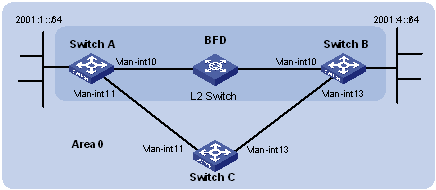
Device | Interface | IPv6 address | Device | Interface | IPv6 address |
Switch A | Vlan-int10 | 2001::1/64 | Switch B | Vlan-int10 | 2001::2/64 |
Vlan-int11 | 2001:2::1/64 | Vlan-int13 | 2001:3::2/64 | ||
Switch C | Vlan-int11 | 2001:2::2/64 | |||
Vlan-int13 | 2001:3::1/64 |
Configuration procedure
Configure IPv6 addresses for the interfaces. (Details not shown.)
Configure basic OSPFv3:
# On Switch A, enable OSPFv3 and specify the router ID as 1.1.1.1.
<SwitchA> system-view
[SwitchA] ospfv3
[SwitchA-ospfv3-1] router-id 1.1.1.1
[SwitchA-ospfv3-1] quit
[SwitchA] interface vlan-interface 10
[SwitchA-Vlan-interface10] ospfv3 1 area 0
[SwitchA-Vlan-interface10] quit
[SwitchA] interface vlan-interface 11
[SwitchA-Vlan-interface11] ospfv3 1 area 0
[SwitchA-Vlan-interface11] quit
# On Switch B, enable OSPFv3 and specify the router ID as 2.2.2.2.
<SwitchB> system-view
[SwitchB] ospfv3
[SwitchB-ospfv3-1] router-id 2.2.2.2
[SwitchB-ospfv3-1] quit
[SwitchB] interface vlan-interface 10
[SwitchB-Vlan-interface10] ospfv3 1 area 0
[SwitchB-Vlan-interface10] quit
[SwitchB] interface vlan-interface 13
[SwitchB-Vlan-interface13] ospfv3 1 area 0
[SwitchB-Vlan-interface13] quit
# On Switch C, enable OSPFv3 and configure the router ID as 3.3.3.3.
<SwitchC> system-view
[SwitchC] ospfv3
[SwitchC-ospfv3-1] router-id 3.3.3.3
[SwitchC-ospfv3-1] quit
[SwitchC] interface vlan-interface 11
[SwitchC-Vlan-interface11] ospfv3 1 area 0
[SwitchC-Vlan-interface11] quit
[SwitchC] interface vlan-interface 13
[SwitchC-Vlan-interface13] ospfv3 1 area 0
[SwitchC-Vlan-interface13] quit
Configure BFD:
# Enable BFD and configure BFD parameters on Switch A.
[SwitchA] bfd session init-mode active
[SwitchA] interface vlan-interface 10
[SwitchA-Vlan-interface10] ospfv3 bfd enable
[SwitchA-Vlan-interface10] bfd min-transmit-interval 500
[SwitchA-Vlan-interface10] bfd min-receive-interval 500
[SwitchA-Vlan-interface10] bfd detect-multiplier 7
[SwitchA-Vlan-interface10] return
# Enable BFD and configure BFD parameters on Switch B.
[SwitchB] bfd session init-mode active
[SwitchB] interface vlan-interface 10
[SwitchB-Vlan-interface10] ospfv3 bfd enable
[SwitchB-Vlan-interface10] bfd min-transmit-interval 500
[SwitchB-Vlan-interface10] bfd min-receive-interval 500
[SwitchB-Vlan-interface10] bfd detect-multiplier 6
Verifying the configuration
# Display the BFD information on Switch A.
<SwitchA> display bfd session

 Total Session Num: 1            Init Mode: Active

 IPv6 Session Working Under Ctrl Mode:

     Local Discr: 1441                Remote Discr: 1450
       Source IP: FE80::20F:FF:FE00:1202 (link-local address of VLAN-interface 10 on Switch A)
  Destination IP: FE80::20F:FF:FE00:1200 (link-local address of VLAN-interface 10 on Switch B)
   Session State: Up                     Interface: Vlan10
       Hold Time: 2319ms
# Display routes destined for 2001:4::0/64 on Switch A.
<SwitchA> display ipv6 routing-table 2001:4::0 64

Summary Count : 1

Destination: 2001:4::/64                                 Protocol  : OSPFv3
NextHop    : FE80::20F:FF:FE00:1200                      Preference: 10
Interface  : Vlan10                                      Cost      : 1
The output information shows that Switch A communicates with Switch B through VLAN-interface 10. The link over VLAN-interface 10 fails.
# Display routes to 2001:4::0/64 on Switch A.
<SwitchA> display ipv6 routing-table 2001:4::0 64

Summary Count : 1

Destination: 2001:4::/64                                 Protocol  : OSPFv3
NextHop    : FE80::BAAF:67FF:FE27:DCD0                   Preference: 10
Interface  : Vlan11                                      Cost      : 2
The output shows that Switch A communicates with Switch B through VLAN-interface 11.