BFD for IPv6 static routes configuration example (indirect next hop)
Network requirements
In Figure 76, Switch A has a route to interface Loopback 1 (2::9/128) on Switch B, with the output interface being VLAN-interface 10. Switch B has a route to interface Loopback 1 (1::9/128) on Switch A, with the output interface being VLAN-interface 12. Switch D has a route to 1::9/128, with the output interface being VLAN-interface 10, and a route to 2::9/128, with the output interface being VLAN-interface 12.
Configure an IPv6 static route to subnet 120::/64 on Switch A, and configure an IPv6 static route to subnet 121::/64 on Switch B. Enable BFD for both routes. Configure an IPv6 static route to subnet 120::/64 and an IPv6 static route to subnet 121::/64 on both Switch C and Switch D. When the link between Switch A and Switch B through Switch D fails, BFD can detect the failure immediately and Switch A and Switch B can communicate through Switch C.
Figure 76: Network diagram
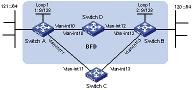
Device | Interface | IPv6 address | Device | Interface | IPv6 address |
Switch A | Vlan-int10 | 12::1/64 | Switch B | Vlan-int12 | 11::2/64 |
Vlan-int11 | 10::102/64 | Vlan-int13 | 13::1/64 | ||
Loop1 | 1::9/128 | Loop1 | 2::9/128 | ||
Switch C | Vlan-int11 | 10::100/64 | Switch D | Vlan-int10 | 12::2/64 |
Vlan-int13 | 13::2/64 | Vlan-int12 | 11::1/64 |
Configuration procedure
Configure IPv6 addresses for interfaces. (Details not shown.)
Configure IPv6 static routes and BFD:
# Configure IPv6 static routes on Switch A and enable BFD control packet mode for the IPv6 static route that traverses Switch D.
<SwitchA> system-view
[SwitchA] interface loopback 1
[SwitchA-LoopBack1] bfd min-transmit-interval 500
[SwitchA-LoopBack1] bfd min-receive-interval 500
[SwitchA-LoopBack1] bfd detect-multiplier 9
[SwitchA-LoopBack1] quit
[SwitchA] ipv6 route-static 120:: 64 2::9 bfd control-packet bfd-source 1::9
[SwitchA] ipv6 route-static 120:: 64 10::100 preference 65
[SwitchA] quit
# Configure IPv6 static routes on Switch B and enable BFD control packet mode for the static route that traverses Switch D.
<SwitchB> system-view
[SwitchB] interface loopback 1
[SwitchB-LoopBack1] bfd min-transmit-interval 500
[SwitchB-LoopBack1] bfd min-receive-interval 500
[SwitchB-LoopBack1] bfd detect-multiplier 9
[SwitchB-LoopBack1] quit
[SwitchB] ipv6 route-static 121:: 64 1::9 bfd control-packet bfd-source 2::9
[SwitchB] ipv6 route-static 121:: 64 13::2 preference 65
[SwitchB] quit
# Configure IPv6 static routes on Switch C.
<SwitchC> system-view
[SwitchC] ipv6 route-static 120:: 64 13::1
[SwitchC] ipv6 route-static 121:: 64 10::102
# Configure IPv6 static routes on Switch D.
<SwitchD> system-view
[SwitchD] ipv6 route-static 120:: 64 11::2
[SwitchD] ipv6 route-static 121:: 64 12::1
Verifying the configuration
# Display the BFD sessions on Switch A.
<SwitchA> display bfd session

 Total Session Num: 1     Up Session Num: 1     Init Mode: Active

 IPv6 Session Working Under Ctrl Mode:

       Local Discr: 513                 Remote Discr: 33
         Source IP: FE80::1:1B49 (link-local address of Loopback1 on Switch A)
    Destination IP: FE80::1:1B49 (link-local address of Loopback1 on Switch B)
     Session State: Up                      Interface: N/A
         Hold Time: 2012ms
The output shows that the BFD session has been created.
# Display the IPv6 static routes on Switch A.
<SwitchA> display ipv6 routing-table protocol static

Summary Count : 1

Static Routing table Status : <Active>
Summary Count : 1

Destination: 120::/64                                    Protocol  : Static
NextHop    : 2::9                                        Preference: 60
Interface  : Vlan10                                      Cost      : 0

Static Routing table Status : <Inactive>
Summary Count : 0
The output shows that Switch A communicates Switch B through VLAN-interface 10. The link over VLAN-interface 10 fails.
# Display IPv6 static routes on Switch A again.
<SwitchA> display ipv6 routing-table protocol static

Summary Count : 1

Static Routing table Status : <Active>
Summary Count : 1

Destination: 120::/64                                    Protocol  : Static
NextHop    : 10::100                                     Preference: 65
Interface  : Vlan11                                      Cost      : 0

Static Routing table Status : <Inactive>
Summary Count : 0
The output shows that Switch A communicates with Switch B through VLAN-interface 11.