BFD for BGP configuration example
Network requirements
As shown in Figure 68,
Configure OSPF as the IGP in AS 200.
Establish two IBGP connections between Switch A and Switch C. When both paths are working, Switch C adopts the path Switch A<—>Switch B<—>Switch C to exchange packets with network 1.1.1.0/24. Configure BFD over the path. If the path fails, BFD can quickly detect the failure and notify it to BGP. Then the path Switch A<—>Switch D<—>Switch C takes effect immediately.
Figure 68: Network diagram
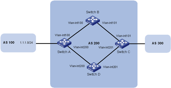
Device | Interface | IP address | Device | Interface | IP address |
Switch A | Vlan-int100 | 3.0.1.1/24 | Switch C | Vlan-int101 | 3.0.2.2/24 |
Vlan-int200 | 2.0.1.1/24 | Vlan-int201 | 2.0.2.2/24 | ||
Switch B | Vlan-int100 | 3.0.1.2/24 | Switch D | Vlan-int200 | 2.0.1.2/24 |
Vlan-int101 | 3.0.2.1/24 | Vlan-int201 | 2.0.2.1/24 |
Configuration procedure
Configure IP addresses for interfaces. (Details not shown.)
Configure OSPF to make sure that Switch A and Switch C are reachable to each other. (Details not shown.)
Configure BGP on Switch A:
# Establish two IBGP connections to Switch C.
<SwitchA> system-view
[SwitchA] bgp 200
[SwitchA-bgp] peer 3.0.2.2 as-number 200
[SwitchA-bgp] peer 2.0.2.2 as-number 200
[SwitchA-bgp] address-family ipv4 unicast
[SwitchA-bgp-ipv4] peer 3.0.2.2 enable
[SwitchA-bgp-ipv4] peer 2.0.2.2 enable
[SwitchA-bgp-ipv4] quit
[SwitchA-bgp] quit
# Create ACL 2000 to permit 1.1.1.0/24 to pass.
[SwitchA] acl number 2000
[SwitchA-acl-basic-2000] rule permit source 1.1.1.0 0.0.0.255
[SwitchA-acl-basic-2000] quit
# Create two route policies, apply_med_50 and apply_med_100. Policy apply_med_50 sets the MED for route 1.1.1.0/24 to 50. Policy apply_med_100 sets that to 100.
[SwitchA] route-policy apply_med_50 permit node 10
[SwitchA-route-policy-apply_med_50-10] if-match ip address acl 2000
[SwitchA-route-policy-apply_med_50-10] apply cost 50
[SwitchA-route-policy-apply_med_50-10] quit
[SwitchA] route-policy apply_med_100 permit node 10
[SwitchA-route-policy-apply_med_100-10] if-match ip address acl 2000
[SwitchA-route-policy-apply_med_100-10] apply cost 100
[SwitchA-route-policy-apply_med_100-10] quit
# Apply routing policy apply_med_50 to routes outgoing to peer 3.0.2.2, and apply routing policy apply_med_100 to routes outgoing to peer 2.0.2.2.
[SwitchA] bgp 200
[SwitchA-bgp] address-family ipv4 unicast
[SwitchA-bgp-ipv4] peer 3.0.2.2 route-policy apply_med_50 export
[SwitchA-bgp-ipv4] peer 2.0.2.2 route-policy apply_med_100 export
[SwitchA-bgp-ipv4] quit
# Enable BFD for peer 3.0.2.2.
[SwitchA-bgp] peer 3.0.2.2 bfd
[SwitchA-bgp] quit
Configure BGP on Switch C:
# Establish two IBGP connections to Switch A.
<SwitchC> system-view
[SwitchC] bgp 200
[SwitchC-bgp] peer 3.0.1.1 as-number 200
[SwitchC-bgp] peer 2.0.1.1 as-number 200
[SwitchC-bgp] address-family ipv4 unicast
[SwitchC-bgp-ipv4] peer 3.0.1.1 enable
[SwitchC-bgp-ipv4] peer 2.0.1.1 enable
[SwitchC-bgp-ipv4] quit
[SwitchC-bgp] quit
# Enable BFD for peer 3.0.1.1.
[SwitchC-bgp] peer 3.0.1.1 bfd
[SwitchC-bgp] quit
[SwitchC] quit
# Display detailed BFD session information on Switch C.
<SwitchC> display bfd session verbose

 Total Session Num: 1     Up Session Num: 1     Init Mode: Active

 IPv4 Session Working Under Ctrl Mode:

       Local Discr: 513                  Remote Discr: 513
         Source IP: 3.0.2.2            Destination IP: 3.0.1.1
     Session State: Up                      Interface: N/A
      Min Tx Inter: 500ms                Act Tx Inter: 500ms
      Min Rx Inter: 500ms                Detect Inter: 2500ms
          Rx Count: 135                      Tx Count: 135
      Connect Type: Indirect           Running Up for: 00:00:58
         Hold Time: 2457ms                  Auth mode: None
       Detect Mode: Async                        Slot: 0
          Protocol: BGP
         Diag Info: No Diagnostic
The output shows that a BFD session has been established between Switch A and Switch C.
# Display BGP peer information on Switch C.
<SwitchC> display bgp peer ipv4

 BGP local router ID: 3.3.3.3
 Local AS number: 200
 Total number of peers: 2                  Peers in established state: 2

  Peer                    AS  MsgRcvd  MsgSent OutQ PrefRcv Up/Down  State

  2.0.1.1                200        4        5    0       0 00:01:55 Established
  3.0.1.1                200        4        5    0       0 00:01:52 Established
The output shows that Switch C has established two BGP connections with Switch A, and both connections are in Established state.
# Display route 1.1.1.0/24 on Switch C.
<SwitchC> display ip routing-table 1.1.1.0 24 verbose

Summary Count : 1

Destination: 1.1.1.0/24
   Protocol: BGP             Process ID: 0
  SubProtID: 0x1                    Age: 00h00m09s
       Cost: 50              Preference: 255
        Tag: 0                    State: Active Adv
  OrigTblID: 0x1                OrigVrf: default-vrf
    TableID: 0x2                 OrigAs: 0
      NBRID: 0x15000001          LastAs: 0
     AttrID: 0x1               Neighbor: 3.0.1.1
      Flags: 0x10060        OrigNextHop: 3.0.1.1
      Label: NULL           RealNextHop: 3.0.2.1
    BkLabel: NULL             BkNextHop: N/A
  Tunnel ID: Invalid          Interface: Vlan-interface101
BkTunnel ID: Invalid        BkInterface: N/A
The output shows that Switch C communicates with network 1.1.1.0/24 through the path Switch C<—>Switch B<—>Switch A.
# Break down the path Switch C<—>Switch B<—>Switch A and then display route 1.1.1.0/24 on Switch C.
<SwitchC> display ip routing-table 1.1.1.0 24 verbose

Summary Count : 1

Destination: 1.1.1.0/24
   Protocol: BGP             Process ID: 0
  SubProtID: 0x1                    Age: 00h03m08s
       Cost: 100             Preference: 255
        Tag: 0                    State: Active Adv
  OrigTblID: 0x1                OrigVrf: default-vrf
    TableID: 0x2                 OrigAs: 0
      NBRID: 0x15000000          LastAs: 0
     AttrID: 0x0               Neighbor: 2.0.1.1
      Flags: 0x10060        OrigNextHop: 2.0.1.1
      Label: NULL           RealNextHop: 2.0.2.1
    BkLabel: NULL             BkNextHop: N/A
  Tunnel ID: Invalid          Interface: Vlan-interface201
BkTunnel ID: Invalid        BkInterface: N/A
The output shows that Switch C communicates with network 1.1.1.0/24 through the path Switch C<—>Switch D<—>Switch A.