BGP path selection configuration example
Network requirements
In Figure 66, all switches run BGP. EBGP runs between Switch A and Switch B, and between Switch A and Switch C. IBGP runs between Switch B and Switch D, and between Switch D and Switch C. OSPF is the IGP protocol in AS 200.
Configure routing policies, making Switch D use the route 1.0.0.0/8 from Switch C as the optimal.
Figure 66: Network diagram
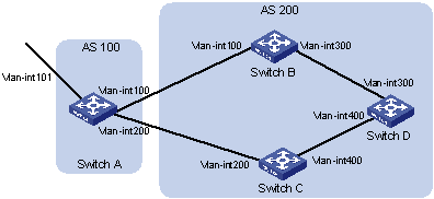
Device | Interface | IP address | Device | Interface | IP address |
Switch A | Vlan-int101 | 1.0.0.1/8 | Switch D | Vlan-int400 | 195.1.1.1/24 |
Vlan-int100 | 192.1.1.1/24 | Vlan-int300 | 194.1.1.1/24 | ||
Vlan-int200 | 193.1.1.1/24 | Switch C | Vlan-int400 | 195.1.1.2/24 | |
Switch B | Vlan-int100 | 192.1.1.2/24 | Vlan-int200 | 193.1.1.2/24 | |
Vlan-int300 | 194.1.1.2/24 |
Configuration procedure
Configure IP addresses for interfaces. (Details not shown.)
Configure OSPF on Switch B, Switch C, and Switch D:
# Configure Switch B.
<SwitchB> system-view
[SwitchB] ospf
[SwitchB-ospf] area 0
[SwitchB-ospf-1-area-0.0.0.0] network 192.1.1.0 0.0.0.255
[SwitchB-ospf-1-area-0.0.0.0] network 194.1.1.0 0.0.0.255
[SwitchB-ospf-1-area-0.0.0.0] quit
[SwitchB-ospf-1] quit
# Configure Switch C.
<SwitchC> system-view
[SwitchC] ospf
[SwitchC-ospf] area 0
[SwitchC-ospf-1-area-0.0.0.0] network 193.1.1.0 0.0.0.255
[SwitchC-ospf-1-area-0.0.0.0] network 195.1.1.0 0.0.0.255
[SwitchC-ospf-1-area-0.0.0.0] quit
[SwitchC-ospf-1] quit
# Configure Switch D.
<SwitchD> system-view
[SwitchD] ospf
[SwitchD-ospf] area 0
[SwitchD-ospf-1-area-0.0.0.0] network 194.1.1.0 0.0.0.255
[SwitchD-ospf-1-area-0.0.0.0] network 195.1.1.0 0.0.0.255
[SwitchD-ospf-1-area-0.0.0.0] quit
[SwitchD-ospf-1] quit
Configure BGP connections:
# Configure Switch A.
<SwitchA> system-view
[SwitchA] bgp 100
[SwitchA-bgp] peer 192.1.1.2 as-number 200
[SwitchA-bgp] peer 193.1.1.2 as-number 200
[SwitchA-bgp] address-family ipv4 unicast
[SwitchA-bgp-ipv4] peer 192.1.1.2 enable
[SwitchA-bgp-ipv4] peer 193.1.1.2 enable
# Inject network 1.0.0.0/8 to the BGP routing table on Switch A.
[SwitchA-bgp-ipv4] network 1.0.0.0 8
[SwitchA-bgp-ipv4] quit
[SwitchA-bgp] quit
# Configure Switch B.
[SwitchB] bgp 200
[SwitchB-bgp] peer 192.1.1.1 as-number 100
[SwitchB-bgp] peer 194.1.1.1 as-number 200
[SwitchB-bgp] address-family ipv4 unicast
[SwitchB-bgp-ipv4] peer 192.1.1.1 enable
[SwitchB-bgp-ipv4] peer 194.1.1.1 enable
[SwitchB-bgp-ipv4] quit
[SwitchB-bgp] quit
# Configure Switch C.
[SwitchC] bgp 200
[SwitchC-bgp] peer 193.1.1.1 as-number 100
[SwitchC-bgp] peer 195.1.1.1 as-number 200
[SwitchC-bgp] address-family ipv4 unicast
[SwitchC-bgp-ipv4] peer 193.1.1.1 enable
[SwitchC-bgp-ipv4] peer 195.1.1.1 enable
[SwitchC-bgp-ipv4] quit
[SwitchC-bgp] quit
# Configure Switch D.
[SwitchD] bgp 200
[SwitchD-bgp] peer 194.1.1.2 as-number 200
[SwitchD-bgp] peer 195.1.1.2 as-number 200
[SwitchD-bgp] address-family ipv4 unicast
[SwitchD-bgp-ipv4] peer 194.1.1.2 enable
[SwitchD-bgp-ipv4] peer 195.1.1.2 enable
[SwitchD-bgp-ipv4] quit
[SwitchD-bgp] quit
Configure attributes for route 1.0.0.0/8, making Switch D give priority to the route learned from Switch C:
(Method 1.) Configure a higher MED value for the route 1.0.0.0/8 advertised from Switch A to peer 192.1.1.2:
# Define an ACL numbered 2000 to permit route 1.0.0.0/8.
[SwitchA] acl number 2000
[SwitchA-acl-basic-2000] rule permit source 1.0.0.0 0.255.255.255
[SwitchA-acl-basic-2000] quit
# Define two routing policies, apply_med_50, which sets the MED for route 1.0.0.0/8 to 50, and apply_med_100, which sets the MED for route 1.0.0.0/8 to 100.
[SwitchA] route-policy apply_med_50 permit node 10
[SwitchA-route-policy-apply_med_50-10] if-match ip address acl 2000
[SwitchA-route-policy-apply_med_50-10] apply cost 50
[SwitchA-route-policy-apply_med_50-10] quit
[SwitchA] route-policy apply_med_100 permit node 10
[SwitchA-route-policy-apply_med_100-10] if-match ip address acl 2000
[SwitchA-route-policy-apply_med_100-10] apply cost 100
[SwitchA-route-policy-apply_med_100-10] quit
# Apply routing policy apply_med_50 to the route advertised to peer 193.1.1.2 (Switch C), and apply_med_100 to the route advertised to peer 192.1.1.2 (Switch B).
[SwitchA] bgp 100
[SwitchA-bgp] address-family ipv4 unicast
[SwitchA-bgp-ipv4] peer 193.1.1.2 route-policy apply_med_50 export
[SwitchA-bgp-ipv4] peer 192.1.1.2 route-policy apply_med_100 export
[SwitchA-bgp-ipv4] quit
[SwitchA-bgp] quit
# Display the BGP routing table on Switch D.
[SwitchD] display bgp routing-table ipv4

 Total number of routes: 2

 BGP local router ID is 195.1.1.1
 Status codes: * - valid, > - best, d - dampened, h - history,
               s - suppressed, S - stale, i - internal, e - external
               Origin: i - IGP, e - EGP, ? - incomplete

     Network            NextHop         MED        LocPrf     PrefVal Path/Ogn

* >i 1.0.0.0            193.1.1.1       50         100        0       100i
*  i                    192.1.1.1       100        100        0       100i
Route 1.0.0.0/8 is the optimal.
(Method 2.) Configure different local preferences on Switch B and C for route 1.0.0.0/8, making Switch D give priority to the route from Switch C:
# Define an ACL numbered 2000 on Switch C, permitting route 1.0.0.0/8.
[SwitchC] acl number 2000
[SwitchC-acl-basic-2000] rule permit source 1.0.0.0 0.255.255.255
[SwitchC-acl-basic-2000] quit
# Configure a routing policy named localpref on Switch C, setting the local preference of route 1.0.0.0/8 to 200 (the default is 100).
[SwitchC] route-policy localpref permit node 10
[SwitchC-route-policy-localpref-10] if-match ip address acl 2000
[SwitchC-route-policy-localpref-10] apply local-preference 200
[SwitchC-route-policy-localpref-10] quit
# Apply routing policy localpref to routes from peer 193.1.1.1.
[SwitchC] bgp 200
[SwitchC-bgp] address-family ipv4 unicast
[SwitchC-bgp-ipv4] peer 193.1.1.1 route-policy localpref import
[SwitchC-bgp-ipv4] quit
[SwitchC-bgp] quit
# Display the BGP routing table on Switch D.
[SwitchD] display bgp routing-table ipv4

 Total number of routes: 2

 BGP local router ID is 195.1.1.1
 Status codes: * - valid, > - best, d - dampened, h - history,
               s - suppressed, S - stale, i - internal, e - external
               Origin: i - IGP, e - EGP, ? - incomplete

     Network            NextHop         MED        LocPrf     PrefVal Path/Ogn

* >i 1.0.0.0            193.1.1.1                  200        0       100i
*  i                    192.1.1.1                  100        0       100i
Route 1.0.0.0/8 learned from Switch C is the optimal.