Basic BGP configuration example
Network requirements
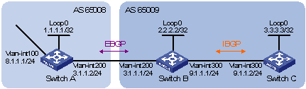
In Figure 59, run EBGP between Switch A and Switch B, and run IBGP between Switch B and Switch C so that Switch C can access the network 8.1.1.0/24 connected to Switch A.
Figure 59: Network diagram
Configuration considerations
To prevent route flapping caused by port state changes, this example uses loopback interfaces to establish IBGP connections. Because loopback interfaces are virtual interfaces, use the peer connect-interface command to specify the loopback interface as the source interface for establishing BGP connections. Enable OSPF in AS 65009 to make sure that Switch B can communicate with Switch C through loopback interfaces.
The EBGP peers, Switch A and Switch B (typically belong to different carriers), are located in different ASs. Typically, their loopback interfaces are not reachable to each other, so directly connected interfaces are used for establishing BGP sessions. To enable Switch C to access the network 8.1.1.0/24 connected directly to Switch A, inject network 8.1.1.0/24 to the BGP routing table of Switch A.
Configuration procedure
Configure IP addresses for interfaces. (Details not shown.)
Configure IBGP:
# Configure Switch B.
<SwitchB> system-view
[SwitchB] bgp 65009
[SwitchB-bgp] router-id 2.2.2.2
[SwitchB-bgp] peer 3.3.3.3 as-number 65009
[SwitchB-bgp] peer 3.3.3.3 connect-interface loopback 0
[SwitchB-bgp] address-family ipv4 unicast
[SwitchB-bgp-ipv4] peer 3.3.3.3 enable
[SwitchB-bgp-ipv4] quit
[SwitchB-bgp] quit
[SwitchB] ospf 1
[SwitchB-ospf-1] area 0
[SwitchB-ospf-1-area-0.0.0.0] network 2.2.2.2 0.0.0.0
[SwitchB-ospf-1-area-0.0.0.0] network 9.1.1.1 0.0.0.255
[SwitchB-ospf-1-area-0.0.0.0] quit
[SwitchB-ospf-1] quit
# Configure Switch C.
<SwitchC> system-view
[SwitchC] bgp 65009
[SwitchC-bgp] router-id 3.3.3.3
[SwitchC-bgp] peer 2.2.2.2 as-number 65009
[SwitchC-bgp] peer 2.2.2.2 connect-interface loopback 0
[SwitchC-bgp] address-family ipv4 unicast
[SwitchC-bgp-ipv4] peer 2.2.2.2 enable
[SwitchC-bgp-ipv4] quit
[SwitchC-bgp] quit
[SwitchC] ospf 1
[SwitchC-ospf-1] area 0
[SwitchC-ospf-1-area-0.0.0.0] network 3.3.3.3 0.0.0.0
[SwitchC-ospf-1-area-0.0.0.0] network 9.1.1.0 0.0.0.255
[SwitchC-ospf-1-area-0.0.0.0] quit
[SwitchC-ospf-1] quit
[SwitchC] display bgp peer ipv4

 BGP local router ID : 3.3.3.3
 Local AS number : 65009
 Total number of peers : 1                 Peers in established state : 1

  Peer                    AS  MsgRcvd  MsgSent OutQ PrefRcv Up/Down  State

  2.2.2.2              65009        2        2    0       0 00:00:13 Established
The output shows that Switch C has established an IBGP peer relationship with Switch B.
Configure EBGP:
# Configure Switch A.
<SwitchA> system-view
[SwitchA] bgp 65008
[SwitchA-bgp] router-id 1.1.1.1
[SwitchA-bgp] peer 3.1.1.1 as-number 65009
[SwitchA-bgp] address-family ipv4 unicast
[SwitchA-bgp-ipv4] peer 3.1.1.1 enable
[SwitchA-bgp-ipv4] network 8.1.1.0 24
[SwitchA-bgp-ipv4] quit
[SwitchA-bgp] quit
# Configure Switch B.
[SwitchB] bgp 65009
[SwitchB-bgp] peer 3.1.1.2 as-number 65008
[SwitchB-bgp] address-family ipv4 unicast
[SwitchB-bgp-ipv4] peer 3.1.1.2 enable
[SwitchB-bgp-ipv4] quit
[SwitchB-bgp] quit
# Display BGP peer information on Switch B.
[SwitchB] display bgp peer ipv4

 BGP local router ID : 2.2.2.2
 Local AS number : 65009
 Total number of peers : 2                 Peers in established state : 2

  Peer                    AS  MsgRcvd  MsgSent OutQ PrefRcv Up/Down  State

  3.3.3.3              65009        4        4    0       0 00:02:49 Established
  3.1.1.2              65008        2        2    0       0 00:00:05 Established
The output shows that Switch B has established an IBGP peer relationship with Switch C and an EBGP peer relationship with Switch A.
# Display the BGP routing table on Switch A.
[SwitchA] display bgp routing-table ipv4

 Total number of routes: 1

 BGP local router ID is 1.1.1.1
 Status codes: * - valid, > - best, d - damped, h - history,
               s - suppressed, S - Stale, i - internal, e - external
               Origin: i - IGP, e - EGP, ? - incomplete

     Network            NextHop         MED        LocPrf     PrefVal Path/Ogn

* >  8.1.1.0/24         8.1.1.1         0                     0       i
# Display the BGP routing table on Switch B.
[SwitchB] display bgp routing-table ipv4

 Total number of routes: 1

 BGP local router ID is 2.2.2.2
 Status codes: * - valid, > - best, d - damped, h - history,
               s - suppressed, S - Stale, i - internal, e - external
               Origin: i - IGP, e - EGP, ? - incomplete

     Network            NextHop         MED        LocPrf     PrefVal Path/Ogn

* >e 8.1.1.0/24         3.1.1.2         0                     0       65008i
# Display the BGP routing table on Switch C.
[SwitchC] display bgp routing-table ipv4

 Total number of routes: 1

 BGP local router ID is 3.3.3.3
 Status codes: * - valid, > - best, d - damped, h - history,
               s - suppressed, S - Stale, i - internal, e - external
               Origin: i - IGP, e - EGP, ? - incomplete

     Network            NextHop         MED        LocPrf     PrefVal Path/Ogn

   i 8.1.1.0/24         3.1.1.2         0          100        0       65008i
The outputs show that Switch A has learned no route to AS 65009, and Switch C has learned network 8.1.1.0, but the next hop 3.1.1.2 is unreachable. As a result, the route is invalid.
Redistribute direct routes:
Configure BGP to redistribute direct routes on Switch B, so that Switch A can obtain the route to 9.1.1.0/24, and Switch C can obtain the route to 3.1.1.0/24.
# Configure Switch B.
[SwitchB] bgp 65009
[SwitchB-bgp] address-family ipv4 unicast
[SwitchB-bgp-ipv4] import-route direct
[SwitchB-bgp-ipv4] quit
[SwitchB-bgp] quit
# Display the BGP routing table on Switch A.
[SwitchA] display bgp routing-table ipv4

 Total number of routes: 4

 BGP local router ID is 1.1.1.1
 Status codes: * - valid, > - best, d - damped, h - history,
               s - suppressed, S - Stale, i - internal, e - external
               Origin: i - IGP, e - EGP, ? - incomplete

     Network            NextHop         MED        LocPrf     PrefVal Path/Ogn

* >e 2.2.2.2/32         3.1.1.1         0                     0       65009?
   e 3.1.1.0/24         3.1.1.1         0                     0       65009?
* >  8.1.1.0/24         8.1.1.1         0                     0       i
* >e 9.1.1.0/24         3.1.1.1         0                     0       65009?
Two routes, 2.2.2.2/32 and 9.1.1.0/24, have been added in Switch A's routing table.
# Display the BGP routing table on Switch C.
[SwitchC] display bgp routing-table ipv4

 Total number of routes: 4

 BGP local router ID is 3.3.3.3
 Status codes: * - valid, > - best, d - damped, h - history,
               s - suppressed, S - Stale, i - internal, e - external
               Origin: i - IGP, e - EGP, ? - incomplete

     Network            NextHop         MED        LocPrf     PrefVal Path/Ogn

   i 2.2.2.2/32         2.2.2.2         0          100        0       ?
* >i 3.1.1.0/24         2.2.2.2         0          100        0       ?
* >i 8.1.1.0/24         3.1.1.2         0          100        0       65008i
* >i 9.1.1.0/24         2.2.2.2         0          100        0       ?
The output shows that the route 8.1.1.0 becomes valid with the next hop as Switch A.
Verifying the configuration
# Ping 8.1.1.1 on Switch C.
[SwitchC] ping 8.1.1.1
Ping 8.1.1.1 (8.1.1.1): 56 data bytes, press CTRL_C to break
56 bytes from 8.1.1.1: icmp_seq=0 ttl=254 time=10.000 ms
56 bytes from 8.1.1.1: icmp_seq=1 ttl=254 time=4.000 ms
56 bytes from 8.1.1.1: icmp_seq=2 ttl=254 time=4.000 ms
56 bytes from 8.1.1.1: icmp_seq=3 ttl=254 time=3.000 ms
56 bytes from 8.1.1.1: icmp_seq=4 ttl=254 time=3.000 ms
--- Ping statistics for 8.1.1.1 ---
5 packet(s) transmitted, 5 packet(s) received, 0.0% packet loss
round-trip min/avg/max/stddev = 3.000/4.800/10.000/2.638 ms