OSPF virtual link configuration example
Network requirements
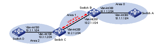
Configure a virtual link between Switch B and Switch C to connect Area 2 to the backbone area. After configuration, Switch B can learn routes to Area 2.
Figure 28: Network diagram
Configuration procedure
Configure IP addresses for interfaces. (Details not shown.)
Enable OSPF:
# Configure Switch A.
<SwitchA> system-view
[SwitchA] ospf 1 router-id 1.1.1.1
[SwitchA-ospf-1] area 0
[SwitchA-ospf-1-area-0.0.0.0] network 10.1.1.0 0.0.0.255
[SwitchA-ospf-1-area-0.0.0.0] quit
# Configure Switch B.
<SwitchB> system-view
[SwitchB] ospf 1 router-id 2.2.2.2
[SwitchB-ospf-1] area 0
[SwitchB-ospf-1-area-0.0.0.0] network 10.1.1.0 0.0.0.255
[SwitchB-ospf-1-area-0.0.0.0] quit
[SwitchB-ospf-1] area 1
[SwitchB–ospf-1-area-0.0.0.1] network 10.2.1.0 0.0.0.255
[SwitchB–ospf-1-area-0.0.0.1] quit
[SwitchB-ospf-1] quit
# Configure Switch C.
<SwitchC> system-view
[SwitchC] ospf 1 router-id 3.3.3.3
[SwitchC-ospf-1] area 1
[SwitchC-ospf-1-area-0.0.0.1] network 10.2.1.0 0.0.0.255
[SwitchC-ospf-1-area-0.0.0.1] quit
[SwitchC-ospf-1] area 2
[SwitchC–ospf-1-area-0.0.0.2] network 10.3.1.0 0.0.0.255
[SwitchC–ospf-1-area-0.0.0.2] quit
[SwitchC-ospf-1] quit
# Configure Switch D.
<SwitchD> system-view
[SwitchD] ospf 1 router-id 4.4.4.4
[SwitchD-ospf-1] area 2
[SwitchD-ospf-1-area-0.0.0.2] network 10.3.1.0 0.0.0.255
[SwitchD-ospf-1-area-0.0.0.2] quit
# Display the OSPF routing table on Switch B.
[SwitchB] display ospf routing

          OSPF Process 1 with Router ID 2.2.2.2
                   Routing Tables
 Routing for Network
 Destination        Cost     Type    NextHop         AdvRouter       Area
 10.2.1.0/24        2        Transit 10.2.1.1        3.3.3.3         0.0.0.1
 10.1.1.0/24        2        Transit 10.1.1.2        2.2.2.2         0.0.0.0
 Total Nets: 2
 Intra Area: 2  Inter Area: 0  ASE: 0  NSSA: 0
Area 0 has no direct connection to Area 2, so the routing table of Switch B has no route to Area 2.
Configure a virtual link:
# Configure Switch B.
[SwitchB] ospf
[SwitchB-ospf-1] area 1
[SwitchB-ospf-1-area-0.0.0.1] vlink-peer 3.3.3.3
[SwitchB-ospf-1-area-0.0.0.1] quit
[SwitchB-ospf-1] quit
# Configure Switch C.
[SwitchC] ospf 1
[SwitchC-ospf-1] area 1
[SwitchC-ospf-1-area-0.0.0.1] vlink-peer 2.2.2.2
[SwitchC-ospf-1-area-0.0.0.1] quit
# Display the OSPF routing table on Switch B.
[SwitchB] display ospf routing

          OSPF Process 1 with Router ID 2.2.2.2
                   Routing Tables

 Routing for Network
 Destination        Cost     Type    NextHop         AdvRouter       Area
 10.2.1.0/24        2        Transit 10.2.1.1        3.3.3.3         0.0.0.1
 10.3.1.0/24        5        Inter   10.2.1.2        3.3.3.3         0.0.0.0
 10.1.1.0/24        2        Transit 10.1.1.2        2.2.2.2         0.0.0.0

 Total Nets: 3
 Intra Area: 2  Inter Area: 1  ASE: 0  NSSA: 0
The output shows that Switch B has learned the route 10.3.1.0/24 to Area 2.