OSPF DR election configuration example
Network requirements
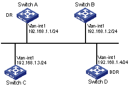
Enable OSPF on Switches A, B, C, and D on the same network.
Configure Switch A as the DR, and configure Switch C as the BDR.
Figure 27: Network diagram
Configuration procedure
Configure IP addresses for interfaces. (Details not shown.)
Enable OSPF:
# Configure Switch A.
<SwitchA> system-view
[SwitchA] router id 1.1.1.1
[SwitchA] ospf
[SwitchA-ospf-1] area 0
[SwitchA-ospf-1-area-0.0.0.0] network 192.168.1.0 0.0.0.255
[SwitchA-ospf-1-area-0.0.0.0] quit
[SwitchA-ospf-1] quit
# Configure Switch B.
<SwitchB> system-view
[SwitchB] router id 2.2.2.2
[SwitchB] ospf
[SwitchB-ospf-1] area 0
[SwitchB-ospf-1-area-0.0.0.0] network 192.168.1.0 0.0.0.255
[SwitchB-ospf-1-area-0.0.0.0] quit
[SwitchB-ospf-1] quit
# Configure Switch C.
<SwitchC> system-view
[SwitchC] router id 3.3.3.3
[SwitchC] ospf
[SwitchC-ospf-1] area 0
[SwitchC-ospf-1-area-0.0.0.0] network 192.168.1.0 0.0.0.255
[SwitchC-ospf-1-area-0.0.0.0] quit
[SwitchC-ospf-1] quit
# Configure Switch D.
<SwitchD> system-view
[SwitchD] router id 4.4.4.4
[SwitchD] ospf
[SwitchD-ospf-1] area 0
[SwitchD-ospf-1-area-0.0.0.0] network 192.168.1.0 0.0.0.255
[SwitchD-ospf-1-area-0.0.0.0] quit
[SwitchD-ospf-1] return
# Display OSPF neighbor information of Switch A.
[SwitchA] display ospf peer verbose

          OSPF Process 1 with Router ID 1.1.1.1
                  Neighbors

 Area 0.0.0.0 interface 192.168.1.1(Vlan-interface1)'s neighbors
 Router ID: 2.2.2.2          Address: 192.168.1.2      GR State: Normal
   State: 2-Way  Mode: None  Priority: 1
   DR: 192.168.1.4  BDR: 192.168.1.3  MTU: 0
   Options is 0x02 (-|-|-|-|-|-|E|-)
   Dead timer due in 38  sec
   Neighbor is up for 00:01:31
   Authentication Sequence: [ 0 ]

 Router ID: 3.3.3.3          Address: 192.168.1.3      GR State: Normal
   State: Full  Mode: Nbr is Master  Priority: 1
   DR: 192.168.1.4  BDR: 192.168.1.3  MTU: 0
   Options is 0x02 (-|-|-|-|-|-|E|-)
   Dead timer due in 31  sec
   Neighbor is up for 00:01:28
   Authentication Sequence: [ 0 ]

 Router ID: 4.4.4.4          Address: 192.168.1.4      GR State: Normal
   State: Full  Mode: Nbr is Master  Priority: 1
   DR: 192.168.1.4  BDR: 192.168.1.3  MTU: 0
   Options is 0x02 (-|-|-|-|-|-|E|-)
   Dead timer due in 31  sec
   Neighbor is up for 00:01:28
   Authentication Sequence: [ 0 ]
The output shows that Switch D is the DR and Switch C is the BDR.
Configure router priorities on interfaces:
# Configure Switch A.
[SwitchA] interface vlan-interface 1
[SwitchA-Vlan-interface1] ospf dr-priority 100
[SwitchA-Vlan-interface1] quit
# Configure Switch B.
[SwitchB] interface vlan-interface 1
[SwitchB-Vlan-interface1] ospf dr-priority 0
[SwitchB-Vlan-interface1] quit
# Configure Switch C.
[SwitchC] interface vlan-interface 1
[SwitchC-Vlan-interface1] ospf dr-priority 2
[SwitchC-Vlan-interface1] quit
# Display neighbor information of Switch D.
<SwitchD> display ospf peer verbose

          OSPF Process 1 with Router ID 4.4.4.4
                  Neighbors

 Area 0.0.0.0 interface 192.168.1.4(Vlan-interface1)'s neighbors
 Router ID: 1.1.1.1      Address: 192.168.1.1      GR State: Normal
   State: Full  Mode:Nbr is  Slave  Priority: 100
   DR: 192.168.1.4  BDR: 192.168.1.3  MTU: 0
   Options is 0x02 (-|-|-|-|-|-|E|-)
   Dead timer due in 31  sec
   Neighbor is up for 00:11:17
   Authentication Sequence: [ 0 ]

 Router ID: 2.2.2.2      Address: 192.168.1.2      GR State: Normal
   State: Full  Mode:Nbr is  Slave  Priority: 0
   DR: 192.168.1.4  BDR: 192.168.1.3  MTU: 0
   Options is 0x02 (-|-|-|-|-|-|E|-)
   Dead timer due in 35  sec
   Neighbor is up for 00:11:19
   Authentication Sequence: [ 0 ]

 Router ID: 3.3.3.3      Address: 192.168.1.3      GR State: Normal
   State: Full  Mode:Nbr is  Slave  Priority: 2
   DR: 192.168.1.4  BDR: 192.168.1.3  MTU: 0
   Options is 0x02 (-|-|-|-|-|-|E|-)
   Dead timer due in 33  sec
   Neighbor is up for 00:11:15
   Authentication Sequence: [ 0 ]
The output shows that the DR and BDR are not changed, because the priority settings do not take effect immediately.
Restart OSPF process:
# Restart the OSPF process of Switch D.
<SwitchD> reset ospf 1 process
Warning : Reset OSPF process? [Y/N]:y
# Display neighbor information of Switch D.
<SwitchD> display ospf peer verbose

          OSPF Process 1 with Router ID 4.4.4.4
                  Neighbors

 Area 0.0.0.0 interface 192.168.1.4(Vlan-interface1)'s neighbors
 Router ID: 1.1.1.1          Address: 192.168.1.1      GR State: Normal
   State: Full  Mode: Nbr is Slave  Priority: 100
   DR: 192.168.1.1  BDR: 192.168.1.3  MTU: 0
   Options is 0x02 (-|-|-|-|-|-|E|-)
   Dead timer due in 39  sec
   Neighbor is up for 00:01:40
   Authentication Sequence: [ 0 ]

 Router ID: 2.2.2.2          Address: 192.168.1.2      GR State: Normal
   State: 2-Way  Mode: None  Priority: 0
   DR: 192.168.1.1  BDR: 192.168.1.3  MTU: 0
   Options is 0x02 (-|-|-|-|-|-|E|-)
   Dead timer due in 35  sec
   Neighbor is up for 00:01:44
   Authentication Sequence: [ 0 ]

 Router ID: 3.3.3.3          Address: 192.168.1.3      GR State: Normal
   State: Full  Mode: Nbr is Slave  Priority: 2
   DR: 192.168.1.1  BDR: 192.168.1.3  MTU: 0
   Options is 0x02 (-|-|-|-|-|-|E|-)
   Dead timer due in 39  sec
   Neighbor is up for 00:01:41
   Authentication Sequence: [ 0 ]
If the neighbor state is full, Switch D has established an adjacency with the neighbor. If the neighbor state is 2-way, the two switches are not the DR or the BDR, and they do not exchange LSAs.
# Display OSPF interface information.
[SwitchA] display ospf interface

          OSPF Process 1 with Router ID 1.1.1.1
                  Interfaces

 Area: 0.0.0.0
 IP Address      Type      State   Cost  Pri   DR             BDR
 192.168.1.1     Broadcast DR      1     100   192.168.1.1    192.168.1.3

[SwitchB] display ospf interface

          OSPF Process 1 with Router ID 2.2.2.2
                  Interfaces

 Area: 0.0.0.0
 IP Address      Type      State    Cost  Pri   DR            BDR
 192.168.1.2     Broadcast DROther  1     0     192.168.1.1   192.168.1.3
The interface state DROther means the interface is not the DR or BDR.