OSPF areas
In large OSPF routing domains, SPF route computations consume too many storage and CPU resources, and enormous OSPF packets generated for route synchronization occupy excessive bandwidth.
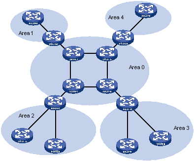
To resolve these issues, OSPF splits an AS into multiple areas. Each area is identified by an area ID. The boundaries between areas are routers rather than links. A network segment (or a link) can only reside in one area as shown in Figure 15.
You can configure route summarization on ABRs to reduce the number of LSAs advertised to other areas and minimize the effect of topology changes.
Figure 15: Area-based OSPF network partition
Backbone area and virtual links
Each AS has a backbone area that distributes routing information between non-backbone areas. Routing information between non-backbone areas must be forwarded by the backbone area. OSPF has the following requirements:
All non-backbone areas must maintain connectivity to the backbone area.
The backbone area must maintain connectivity within itself.
In practice, these requirements might not be met due to lack of physical links. OSPF virtual links can solve this issue.
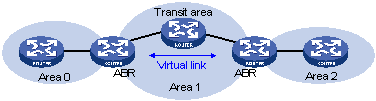
A virtual link is established between two ABRs through a non-backbone area. It must be configured on both ABRs to take effect. The non-backbone area is called a transit area.
In Figure 16, Area 2 has no direct physical link to the backbone Area 0. You can configure a virtual link between the two ABRs to connect Area 2 to the backbone area.
Figure 16: Virtual link application 1
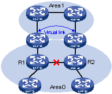
Virtual links can also be used to provide redundant links. If the backbone area cannot maintain internal connectivity because of the failure of a physical link, you can configure a virtual link to replace the failed physical link, as shown in Figure 17.
Figure 17: Virtual link application 2
The virtual link between the two ABRs acts as a point-to-point connection. You can configure interface parameters, such as hello interval, on the virtual link as they are configured on a physical interface.
The two ABRs on the virtual link unicast OSPF packets to each other, and the OSPF routers in between convey these OSPF packets as normal IP packets.
Stub area and totally stub area
A stub area does not distribute Type-5 LSAs to reduce the routing table size and LSAs advertised within the area. The ABR of the stub area advertises a default route in a Type-3 LSA so that the routers in the area can reach external networks through the default route.
To further reduce the routing table size and advertised LSAs, you can configure the stub area as a totally stub area. The ABR of a totally stub area does no advertise inter-area routes or external routes. It advertises a default route in a Type-3 LSA so that the routers in the area can reach external networks through the default route.
NSSA area and totally NSSA area
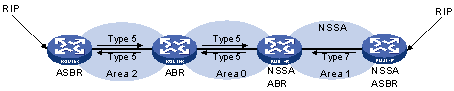
An NSSA area does not import AS external LSAs (Type-5 LSAs) but can import Type-7 LSAs generated by the NSSA ASBR. The NSSA ABR translates Type-7 LSAs into Type-5 LSAs and advertises the Type-5 LSAs to other areas.
In Figure 18, the OSPF AS contains Area 1, Area 2, and Area 0. The other two ASs run RIP. Area 1 is an NSSA area where the ASBR redistributes RIP routes in Type-7 LSAs into Area 1. Upon receiving the Type-7 LSAs, the NSSA ABR translates them to Type-5 LSAs, and advertises the Type-5 LSAs to Area 0.
The ASBR of Area 2 redistributes RIP routes in Type-5 LSAs into the OSPF routing domain. However, Area 1 does not receive Type-5 LSAs because it is an NSSA area.
Figure 18: NSSA area