Configuring RIP to advertise a summary route
Network requirements
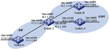
As shown in Figure 10, Switch A and Switch B run OSPF, Switch D runs RIP, and Switch C runs OSPF and RIP. Configure RIP to redistribute OSPF routes on Switch C so Switch D can learn routes destined for networks 10.1.1.0/24, 10.2.1.0/24, 10.5.1.0/24, and 10.6.1.0/24.
To reduce the routing table size of Switch D, configure route summarization on Switch C to advertise only the summary route 10.0.0.0/8 to Switch D.
Figure 10: Network diagram
Configuration procedure
Configure IP addresses for interfaces. (Details not shown.)
Configure basic OSPF:
# Configure Switch A.
<SwitchA> system-view
[SwitchA] ospf
[SwitchA-ospf-1] area 0
[SwitchA-ospf-1-area-0.0.0.0] network 10.5.1.0 0.0.0.255
[SwitchA-ospf-1-area-0.0.0.0] network 10.2.1.0 0.0.0.255
[SwitchA-ospf-1-area-0.0.0.0] quit
# Configure Switch B.
<SwitchB> system-view
[SwitchB] ospf
[SwitchB-ospf-1] area 0
[SwitchB-ospf-1-area-0.0.0.0] network 10.1.1.0 0.0.0.255
[SwitchB-ospf-1-area-0.0.0.0] network 10.6.1.0 0.0.0.255
[SwitchB-ospf-1-area-0.0.0.0] quit
# Configure Switch C.
<SwitchC> system-view
[SwitchC] ospf
[SwitchC-ospf-1] area 0
[SwitchC-ospf-1-area-0.0.0.0] network 10.1.1.0 0.0.0.255
[SwitchC-ospf-1-area-0.0.0.0] network 10.2.1.0 0.0.0.255
[SwitchC-ospf-1-area-0.0.0.0] quit
[SwitchC-ospf-1] quit
Configure basic RIP:
# Configure Switch C.
[SwitchC] rip 1
[SwitchC-rip-1] network 11.3.1.0
[SwitchC-rip-1] version 2
[SwitchC-rip-1] undo summary
# Configure Switch D.
<SwitchD> system-view
[SwitchD] rip 1
[SwitchD-rip-1] network 11.0.0.0
[SwitchD-rip-1] version 2
[SwitchD-rip-1] undo summary
[SwitchD-rip-1] quit
# Configure RIP to redistribute routes from OSPF process 1 and direct routes on Switch C.
[SwitchC-rip-1] import-route direct
[SwitchC-rip-1] import-route ospf 1
[SwitchC-rip-1] quit
# Display the IP routing table on Switch D.
[SwitchD] display ip routing-table

Destinations : 15        Routes : 15

Destination/Mask    Proto  Pre  Cost         NextHop         Interface
0.0.0.0/32          Direct 0    0            127.0.0.1       InLoop0
10.1.1.0/24         RIP    100  1            11.3.1.1        Vlan300
10.2.1.0/24         RIP    100  1            11.3.1.1        Vlan300
10.5.1.0/24         RIP    100  1            11.3.1.1        Vlan300
10.6.1.0/24         RIP    100  1            11.3.1.1        Vlan300
11.3.1.0/24         Direct 0    0            11.3.1.2        Vlan300
11.3.1.0/32         Direct 0    0            11.3.1.2        Vlan300
11.3.1.2/32         Direct 0    0            127.0.0.1       InLoop0
11.4.1.0/24         Direct 0    0            11.4.1.2        Vlan400
11.4.1.0/32         Direct 0    0            11.4.1.2        Vlan400
11.4.1.2/32         Direct 0    0            127.0.0.1       InLoop0
127.0.0.0/8         Direct 0    0            127.0.0.1       InLoop0
127.0.0.0/32        Direct 0    0            127.0.0.1       InLoop0
127.0.0.1/32        Direct 0    0            127.0.0.1       InLoop0
127.255.255.255/32  Direct 0    0            127.0.0.1       InLoop0
Configure route summarization:
# Configure route summarization on Switch C and advertise only the summary route 10.0.0.0/8.
[SwitchC] interface vlan-interface 300
[SwitchC-Vlan-interface300] rip summary-address 10.0.0.0 8
# Display the IP routing table on Switch D.
[SwitchD] display ip routing-table

Destinations : 12        Routes : 12

Destination/Mask    Proto  Pre  Cost         NextHop         Interface
0.0.0.0/32          Direct 0    0            127.0.0.1       InLoop0
10.0.0.0/8          RIP    100  1            11.3.1.1        Vlan300
11.3.1.0/24         Direct 0    0            11.3.1.2        Vlan300
11.3.1.0/32         Direct 0    0            11.3.1.2        Vlan300
11.3.1.2/32         Direct 0    0            127.0.0.1       InLoop0
11.4.1.0/24         Direct 0    0            11.4.1.2        Vlan400
11.4.1.0/32         Direct 0    0            11.4.1.2        Vlan400
11.4.1.2/32         Direct 0    0            127.0.0.1       InLoop0
127.0.0.0/8         Direct 0    0            127.0.0.1       InLoop0
127.0.0.0/32        Direct 0    0            127.0.0.1       InLoop0
127.0.0.1/32        Direct 0    0            127.0.0.1       InLoop0
127.255.255.255/32  Direct 0    0            127.0.0.1       InLoop0