Connecting the switch to the network through a fiber Ethernet port
Use an optical fiber to connect an XFP, SFP, CFP, SFP+, or QSFP+ port on the switch to the network. You must install a transceiver module to the switch, and then insert the fiber connector to the module.
Introduction to fiber connector
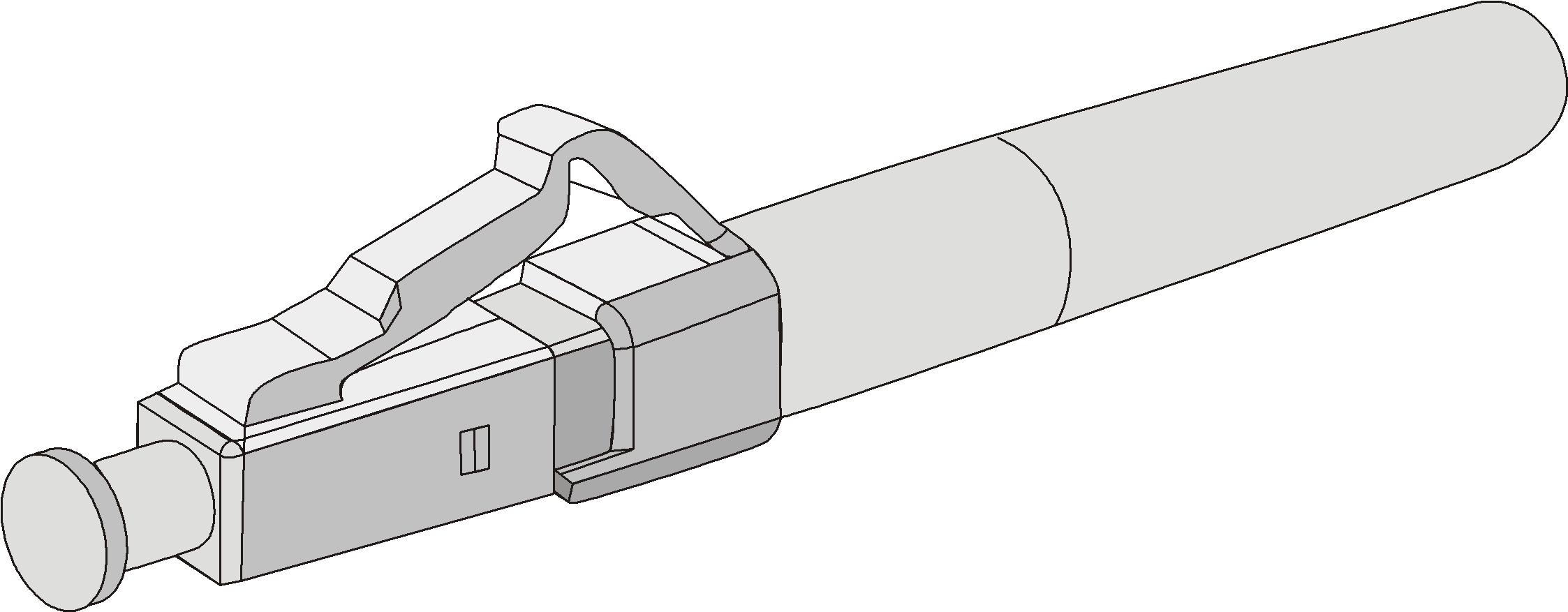
Fiber connectors are indispensable passive components in an optical fiber communication system. They allow the removable connection between optical channels, which makes the optical system debugging and maintenance more convenient and the transit dispatching of the system more flexible. Among various fiber connectors, only the LC connector is described here.
Figure 42: LC connector
Precautions
Follow these precautionary steps:
When selecting a fiber network facility, make sure the type of the connector and the fiber matches the adopted fiber port.
Be sure to install the dust cover if the fiber port is not connected to a fiber connector.
Some invisible rays might be emitted from the fiber port if the fiber port is not connected to a fiber connector or the dust cover is removed. Therefore, never stare at the fiber port directly.
Never bend or curve a fiber when connecting it.
Installing the XFP, SFP, SFP+, and QSFP+ modules
![[CAUTION: ]](images/caution.png) | CAUTION: Do not touch the golden finger of a transceiver module during installation. | |
The installation of the XFP, SFP, SFP+, and QSFP+ modules is similar. This section uses an SFP+ module as an example.
To install an SFP+ module:
Remove the optical fiber if the SPF+ module is installed with an optical fiber.
Put on an ESD wrist strap, and make sure it has close skin contact, and is correctly grounded.
Unpack the SFP+ module and make sure the clasp is closed.
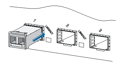
Gently insert the SFP+ module into the port until it fits in completely, as shown in Figure 43.
Figure 43: Installing an SFP+ module
![[IMPORTANT: ]](images/important.png)
IMPORTANT:
Do not remove the dust plug of the SFP+ module port before installing an optical fiber.
Installing the CFP module
Put on an ESD wrist strap. Make sure it has close skin contact and is correctly grounded.
Unpack the CFP module.
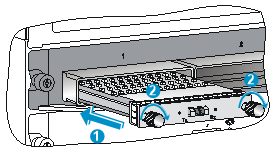
Insert the CFP module gently into the port until it fits in completely.
Fasten the captive screws on the CFP module.
Figure 44: Installing a 40-Gbps CFP transceiver module
![[NOTE: ]](images/note.png)
NOTE:
Unsmooth installation for the 40-Gbps CFP module is likely to occur due to the bump design on its top.
The appearance of 100-Gbps CFP module differs from that of the 40-Gbps CFP module.
Connecting an optical fiber
Put on an ESD wrist strap, and make sure it has close skin contact, and is correctly grounded.
Remove the dust plug from the fiber connector, and use dust free paper and absolute alcohol to clean the end face of the fiber connector.
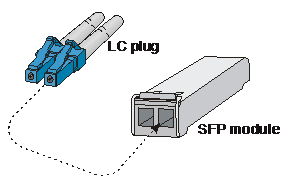
Figure 45: LC fiber connector
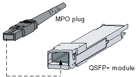
Figure 46: MPO fiber connector
Connect one end of the fiber to the SFP module of the 12500E switch.
Connect the other end of the fiber to the peer device.
Connecting an SFP+ cable and a QSFP+ cable (optional)
The installation of the SFP+ cable and QSFP+ cable is similar. This section uses an SFP+ cable as an example.
| NOTE:
| |
To connect an SFP+ cable:
Wear an ESD wrist strap and make sure the strap has a good skin contact and is correctly grounded.
Unpack the SFP+ cable.
Insert one end of the plug of the SFP+ cable horizontally into the SFP+ slot on the switch and the other end of the plug into the SFP+ slot of the peer device.
Figure 47: Connecting the SFP+ cable
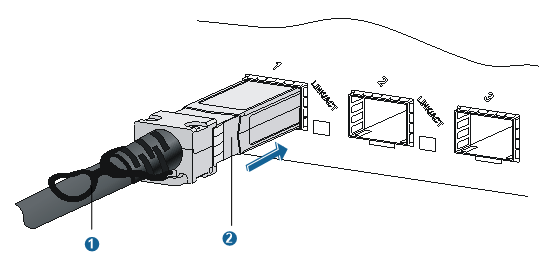
(1) Pull latch | (2) Connector |