Installation procedure
Each 12500E switch has keyhole standoffs on its cable management bracket and keyholes on the chassis for securing the cable management bracket to the chassis. See Figure 10.
Figure 10: Keyhole standoff and keyhole
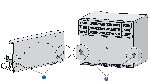
(1) Keyhole standoff | (2) Keyhole |
Installing an upper expansion cable management bracket
Holding the notches on both sides of the chassis panel above the upper cable management bracket, gently remove the panel.
Pressing the two sides of the front panel, pivot the power frame front panel upward.
Loosen the fastening screws on the upper cable management bracket with a Phillips screwdriver.
Align the keyhole standoffs on the rear of the cable management bracket with the keyholes on the chassis and remove the cable management bracket.
Align the keyhole standoffs on the upper expansion cable management bracket (with a mark) with the keyholes on the chassis.
Push the expansion cable management bracket forward until it makes close contact with the chassis. Then pull the expansion cable management bracket downwards a little until the keyhole standoff fits into the keyhole on the chassis.
Unpack the screws come with the expansion cable management bracket and fasten them with a Phillips screwdriver to secure the expansion cable management bracket to the chassis.
Close the power frame front panel.
Figure 11: Installing an upper expansion cable management bracket
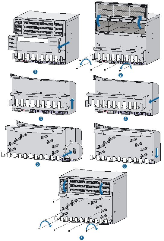
Installing a lower expansion cable management bracket
Remove the filler panel or card on the front panel. For how to remove them, see "Replacement procedures."
Loosen the fastening screws on the lower cable management bracket with a Phillips screwdriver.
Align the keyhole standoffs on the rear of the lower cable management bracket with the keyholes on the chassis and remove the cable management bracket.
Align the keyhole standoffs on the lower expansion cable management bracket (with no mark) with the keyholes on the chassis.
Push the expansion cable management bracket forward until it makes close contact with the chassis. Then pull the expansion cable management bracket downwards until the keyhole standoff fits into the keyhole on the chassis.
Unpack the screws come with the expansion cable management bracket and fasten them with a Phillips screwdriver to secure the expansion cable management bracket to the chassis.
Install the removed filler panel or card. For more information, see "Installing a card."
For illustration of the installation procedure for a lower cable management bracket, see callouts 2 to 7 in Figure 11.