OSPFv3 DR election configuration example
Network requirements
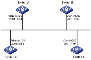
As shown in Figure 105:
Configure router priority 100 for Switch A, the highest priority on the network, so it will become the DR.
Configure router priority 2 for Switch C, the second highest priority on the network, so it will become the BDR.
Configure router priority 0 for Switch B, so it cannot become a DR or BDR.
Switch D uses the default router priority 1.
Figure 105: Network diagram
Configuration procedure
Configure IPv6 addresses for interfaces. (Details not shown.)
Configure basic OSPFv3:
# On Switch A, enable OSPFv3 and specify the router ID as 1.1.1.1.
<SwitchA> system-view
[SwitchA] ospfv3
[SwitchA-ospfv3-1] router-id 1.1.1.1
[SwitchA-ospfv3-1] quit
[SwitchA] interface vlan-interface 100
[SwitchA-Vlan-interface100] ospfv3 1 area 0
[SwitchA-Vlan-interface100] quit
# On Switch B, enable OSPFv3 and specify the router ID as 2.2.2.2.
<SwitchB> system-view
[SwitchB] ospfv3
[SwitchB-ospfv3-1] router-id 2.2.2.2
[SwitchB-ospfv3-1] quit
[SwitchB] interface vlan-interface 200
[SwitchB-Vlan-interface200] ospfv3 1 area 0
[SwitchB-Vlan-interface200] quit
# On Switch C, enable OSPFv3 and specify the router ID as 3.3.3.3.
<SwitchC> system-view
[SwitchC] ospfv3
[SwitchC-ospfv3-1] router-id 3.3.3.3
[SwitchC-ospfv3-1] quit
[SwitchC] interface vlan-interface 100
[SwitchC-Vlan-interface100] ospfv3 1 area 0
[SwitchC-Vlan-interface100] quit
# On Switch D, enable OSPFv3 and specify the router ID as 4.4.4.4.
<SwitchD> system-view
[SwitchD] ospfv3
[SwitchD-ospfv3-1] router-id 4.4.4.4
[SwitchD-ospfv3-1] quit
[SwitchD] interface vlan-interface 200
[SwitchD-Vlan-interface200] ospfv3 1 area 0
[SwitchD-Vlan-interface200] quit
# Display neighbor information on Switch A. The switches have the same default DR priority 1, so Switch D (the switch with the highest router ID) is elected as the DR, and Switch C is the BDR.
[SwitchA] display ospfv3 peer

               OSPFv3 Process 1 with Router ID 1.1.1.1

 Area: 0.0.0.0
-------------------------------------------------------------------------
 Router ID       Pri State             Dead-Time InstID Interface
 2.2.2.2         1   2-Way/DROther     00:00:36  0      Vlan200
 3.3.3.3         1   Full/BDR          00:00:35  0      Vlan100
 4.4.4.4         1   Full/DR           00:00:33  0      Vlan200
# Display neighbor information on Switch D. The neighbor states are all full.
[SwitchD] display ospfv3 peer

               OSPFv3 Process 1 with Router ID 4.4.4.4

 Area: 0.0.0.0
-------------------------------------------------------------------------
 Router ID       Pri State             Dead-Time InstID Interface
 1.1.1.1         1   Full/DROther      00:00:30  0      Vlan100
 2.2.2.2         1   Full/DROther      00:00:37  0      Vlan200
 3.3.3.3         1   Full/BDR          00:00:31  0      Vlan100
Configure router priorities for interfaces:
# Set the router priority of VLAN-interface 100 to 100 on Switch A.
[SwitchA] interface Vlan-interface 100
[SwitchA-Vlan-interface100] ospfv3 dr-priority 100
[SwitchA-Vlan-interface100] quit
# Set the router priority of VLAN-interface 200 to 0 on Switch B.
[SwitchB] interface vlan-interface 200
[SwitchB-Vlan-interface200] ospfv3 dr-priority 0
[SwitchB-Vlan-interface200] quit
# Set the router priority of VLAN-interface 100 to 2 on Switch C.
[SwitchC] interface Vlan-interface 100
[SwitchC-Vlan-interface100] ospfv3 dr-priority 2
[SwitchC-Vlan-interface100] quit
# Display neighbor information on Switch A. Router priorities have been updated, but the DR and BDR are not changed.
[SwitchA] display ospfv3 peer

               OSPFv3 Process 1 with Router ID 1.1.1.1

 Area: 0.0.0.0
-------------------------------------------------------------------------
 Router ID       Pri State             Dead-Time InstID Interface
 2.2.2.2         0   2-Way/DROther     00:00:36  0      Vlan200
 3.3.3.3         2   Full/BDR          00:00:35  0      Vlan200
 4.4.4.4         1   Full/DR           00:00:33  0      Vlan200
# Display neighbor information on Switch D. Switch D is still the DR.
[SwitchD] display ospfv3 peer

               OSPFv3 Process 1 with Router ID 4.4.4.4

 Area: 0.0.0.0
-------------------------------------------------------------------------
 Router ID       Pri State             Dead-Time InstID Interface
 1.1.1.1         100 Full/DROther      00:00:30  0      Vlan100
 2.2.2.2         0   Full/DROther      00:00:37  0      Vlan200
 3.3.3.3         2   Full/BDR          00:00:31  0      Vlan100
Restart DR and BDR election:
# Use the shutdown and undo shutdown commands on interfaces to restart DR and BDR election. (Details not shown.)
# Display neighbor information on Switch A. The output shows that Switch C becomes the BDR.
[SwitchA] display ospfv3 peer

               OSPFv3 Process 1 with Router ID 1.1.1.1

 Area: 0.0.0.0
-------------------------------------------------------------------------
 Router ID       Pri State             Dead-Time InstID Interface
 2.2.2.2         0   Full/DROther      00:00:36  0      Vlan200
 3.3.3.3         2   Full/BDR          00:00:35  0      Vlan100
 4.4.4.4         1   Full/DROther      00:00:33  0      Vlan200
# Display neighbor information on Switch D.
[SwitchD] display ospfv3 peer

               OSPFv3 Process 1 with Router ID 4.4.4.4

 Area: 0.0.0.0
-------------------------------------------------------------------------
 Router ID       Pri State             Dead-Time InstID Interface
 1.1.1.1         100 Full/DR           00:00:30  0      Vlan100
 2.2.2.2         0   2-Way/DROther     00:00:37  0      Vlan200
 3.3.3.3         2   Full/BDR          00:00:31  0      Vlan100
The output shows that Switch A becomes the DR.