RIPng NSR configuration example
Network requirements
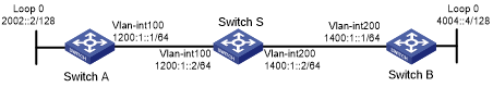
As shown in Figure 99, Switch S, Switch A, and Switch B learn IPv6 routing information through RIPng.
Enable RIPng NSR on Switch S to ensure correct routing when an active/standby switchover occurs on Switch S.
Figure 99: Network diagram
Configuration procedure
Configure IPv6 addresses for interfaces. (Details not shown.)
Configure RIPng on the switches to ensure the following: (Details not shown.)
Switch S, Switch A, and Switch B can communicate with each other at Layer 3.
Dynamic route update can be implemented among them with RIPng.
Enable RIPng NSR on Switch S.
<SwitchS> system-view
[SwitchS] ripng 1
[SwitchS-ripng-1] non-stop-routing
[SwitchS-ripng-1] quit
Verifying the configuration
# Perform an active/standby switchover on Switch S.
[SwitchS] placement reoptimize
Predicted changes to the placement
Program                           Current location       New location
---------------------------------------------------------------------
lb                                0/0                    0/0
lsm                               0/0                    0/0
slsp                              0/0                    0/0
rib6                              0/0                    0/0
routepolicy                       0/0                    0/0
rib                               0/0                    0/0
staticroute6                      0/0                    0/0
staticroute                       0/0                    0/0
eviisis                           0/0                    0/0
ospf                              0/0                    1/0
Continue? [y/n]:y
Re-optimization of the placement start. You will be notified on completion
Re-optimization of the placement complete. Use 'display placement' to view the new placement
# During the switchover period, display RIPng neighbors on Switch A to verify the neighbor relationship between Switch A and Switch S.
[SwitchA] display ripng 1 neighbor
 Neighbor Address: FE80::AE45:5CE7:422E:2867
     Interface  : Vlan-interface100
     Version    : RIPng version 1     Last update: 00h00m23s
     Bad packets: 0                   Bad routes : 0
# Display RIPng routes on Switch A to verify if Switch A has a route to the loopback interface on Switch B.
[SwitchA] display ripng 1 route
   Route Flags: A - Aging, S - Suppressed, G - Garbage-collect, D - Direct
                O - Optimal, F - Flush to RIB
 ----------------------------------------------------------------
 Peer FE80::AE45:5CE7:422E:2867 on Vlan-interface100
 Destination 1400:1::/64,
     via FE80::AE45:5CE7:422E:2867, cost 1, tag 0, AOF, 1 secs
 Destination 4004::4/128,
     via FE80::AE45:5CE7:422E:2867, cost 2, tag 0, AOF, 1 secs
 Local route
 Destination 2002::2/128,
     via ::, cost 0, tag 0, DOF
 Destination 1200:1::/64,
     via ::, cost 0, tag 0, DOF
# Display RIPng neighbors on Switch B to verify the neighbor relationship between Switch B and Switch S.
[SwitchB] display ripng 1 neighbor
 Neighbor Address: FE80::20C:29FF:FECE:6277
     Interface  : Vlan-interface200
     Version    : RIPng version 1     Last update: 00h00m18s
     Bad packets: 0                   Bad routes : 0
# Display RIPng routes on Switch B to verify if Switch B has a route to the loopback interface on Switch A.
[SwitchB] display ripng 1 route
   Route Flags: A - Aging, S - Suppressed, G - Garbage-collect, D - Direct
                O - Optimal, F - Flush to RIB
 ----------------------------------------------------------------
 Peer FE80::20C:29FF:FECE:6277 on Vlan-interface200
 Destination 2002::2/128,
     via FE80::20C:29FF:FECE:6277, cost 2, tag 0, AOF, 24 secs
 Destination 1200:1::/64,
     via FE80::20C:29FF:FECE:6277, cost 1, tag 0, AOF, 24 secs
 Local route
 Destination 4004::4/128,
     via ::, cost 0, tag 0, DOF
 Destination 1400:1::/64,
     via ::, cost 0, tag 0, DOF
The output shows the following when an active/standby switchover occurs on Switch S:
The neighbor relationships and routing information on Switch A and Switch B have not changed.
The traffic from Switch A to Switch B has not been impacted.