IPv6 multicast BGP configuration example
Network requirements
As shown in Figure 88, OSPFv3 runs within AS 100 and AS 200 to ensure intra-AS connectivity. IPv6 MBGP runs between the two ASs to exchange IPv6 unicast routes used for RPF check.
Enable Anycast RP on Switch A and Switch B.
Figure 88: Network diagram
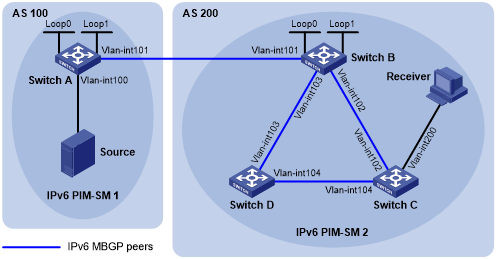
Table 22: Interface and IP address assignment
Device | Interface | IP address | Device | Interface | IP address |
|---|---|---|---|---|---|
Source | - | 1002::100/64 | Switch B | Vlan-int101 | 1001::2/64 |
Switch A | Vlan-int100 | 1002::1/64 | Vlan-int102 | 2001::1/64 | |
Vlan-int101 | 1001::1/64 | Vlan-int103 | 2002::1/64 | ||
Loop0 | 1:1::1/128 | Loop0 | 1:1::1/128 | ||
Loop1 | 1:1::2/128 | Loop1 | 2:2::2/128 | ||
Switch C | Vlan-int200 | 3002::1/64 | Switch D | Vlan-int103 | 2002::2/64 |
Vlan-int102 | 2001::2/64 | Vlan-int104 | 3001::2/64 | ||
Vlan-int104 | 3001::1/64 |
Configuration procedure
Configure IPv6 addresses for interfaces and configure OSPFv3 (this example uses OSPFv3 process 1) in AS 200 to ensure intra-AS connectivity. (Details not shown.)
Enable IPv6 multicast routing, IPv6 PIM-SM, and MLD, and configure BSR boundaries:
# On Switch A, enable IPv6 multicast routing globally, and enable IPv6 PIM-SM on interfaces.
<SwitchA> system-view
[SwitchA] ipv6 multicast routing
[SwitchA-mrib6] quit
[SwitchA] interface vlan-interface 100
[SwitchA-Vlan-interface100] ipv6 pim sm
[SwitchA-Vlan-interface100] quit
[SwitchA] interface vlan-interface 101
[SwitchA-Vlan-interface101] ipv6 pim sm
[SwitchA-Vlan-interface101] quit
[SwitchA] interface loopback 0
[SwitchA-LoopBack0] ipv6 pim sm
[SwitchA-LoopBack0] quit
# Configure Switch B and Switch D in the same way that Switch A was configured.
# On Switch C, enable IPv6 multicast routing globally.
<SwitchC> system-view
[SwitchC] ipv6 multicast routing
[SwitchC-mrib6] quit
# Enable IPv6 PIM-SM on interfaces, and enable MLD on VLAN-interface 200.
[SwitchC] interface vlan-interface 102
[SwitchC-Vlan-interface102] ipv6 pim sm
[SwitchC-Vlan-interface102] quit
[SwitchC] interface vlan-interface 104
[SwitchC-Vlan-interface104] ipv6 pim sm
[SwitchC-Vlan-interface104] quit
[SwitchC] interface vlan-interface 200
[SwitchC-Vlan-interface200] ipv6 pim sm
[SwitchC-Vlan-interface200] mld enable
[SwitchC-Vlan-interface200] quit
# Configure the BSR boundary on Switch A.
[SwitchA] interface vlan-interface 101
[SwitchA-Vlan-interface101] ipv6 pim bsr-boundary
[SwitchA-Vlan-interface101] quit
# Configure the BSR boundary on Switch B.
[SwitchB] interface vlan-interface 101
[SwitchB-Vlan-interface101] ipv6 pim bsr-boundary
[SwitchB-Vlan-interface101] quit
Enable Anycast RP, and specify C-BSR and C-RP:
# Configure Switch A.
[SwitchA] ipv6 pim
[SwitchA-pim6] anycast-rp 1:1::1 1:1::2
[SwitchA-pim6] anycast-rp 1:1::1 2:2::2
[SwitchA-pim6] c-bsr 1:1::1
[SwitchA-pim6] c-rp 1:1::1
[SwitchA-pim6] quit
# Configure Switch B.
[SwitchB] ipv6 pim
[SwitchB-pim6] anycast-rp 1:1::1 1:1::2
[SwitchB-pim6] anycast-rp 1:1::1 2:2::2
[SwitchB-pim6] c-bsr 1:1::1
[SwitchB-pim6] c-rp 1:1::1
[SwitchB-pim6] quit
Configure BGP to establish BGP IPv6 multicast peers and redistribute routes:
# On Switch A, establish an EBGP session to Switch B.
[SwitchA] bgp 100
[SwitchA-bgp-default] router-id 1.1.1.1
[SwitchA-bgp-default] peer 1001::2 as-number 200
# Enable exchange of IPv6 unicast routes used for RPF check with Switch B.
[SwitchA-bgp-default] address-family ipv6 multicast
[SwitchA-bgp-default-mul-ipv6] peer 1001::2 enable
# Redistribute direct routes into BGP.
[SwitchA-bgp-default-mul-ipv6] import-route direct
[SwitchA-bgp-default-mul-ipv6] quit
# On Switch B, establish an EBGP session to Switch A.
[SwitchB] bgp 200
[SwitchB-bgp-default] router-id 2.2.2.2
[SwitchB-bgp-default] peer 1001::1 as-number 100
# Enable exchange of IPv6 unicast routes used for RPF check with Switch B.
[SwitchB-bgp-default] address-family ipv6 multicast
[SwitchB-bgp-default-mul-ipv6] peer 1001::1 enable
# Redistribute OSPFv3 routes into BGP.
[SwitchB-bgp-default-mul-ipv6] import-route ospfv3 1
[SwitchB-bgp-default-mul-ipv6] quit
Establish BGP IPv6 unicast peer relationships between Switch A and Switch B and redistribute routes:
# On Switch A, enable BGP to exchange IPv6 unicast routes with Switch B, and redistribute direct routes into BGP.
[SwitchA-bgp-default] address-family ipv6 unicast
[SwitchA-bgp-default-ipv6] peer 1001::2 enable
[SwitchA-bgp-default-ipv6] import-route direct
[SwitchA-bgp-default-ipv6] quit
[SwitchA-bgp-default] quit
# On Switch B, enable BGP to exchange IPv6 unicast routes with Switch A, and redistribute direct routes into BGP.
[SwitchB-bgp-default] address-family ipv6 unicast
[SwitchB-bgp-default-ipv6] peer 1001::1 enable
[SwitchB-bgp-default-ipv6] import-route direct
[SwitchB-bgp-default-ipv6] quit
[SwitchB-bgp-default] quit
Verifying the configuration
# Verify the BGP IPv6 multicast peer information on Switch B.
[SwitchB] display bgp peer ipv6 multicast

 BGP local router ID : 2.2.2.2
 Local AS number : 200
 Total number of peers : 3                 Peers in established state : 3

  Peer        AS  MsgRcvd  MsgSent  OutQ PrefRcv Up/Down  State

  1001::1     100       56       56      0        0 00:40:54 Established
# Verify the RPF information for the multicast source on Switch B.
[SwitchB] display ipv6 multicast rpf-info 1002::1
 RPF information about source 1002::1:
     RPF interface: Vlan-interface101, RPF neighbor: 1001::1
     Referenced prefix/prefix length: 1002::/64
     Referenced route type: mbgp
     Route selection rule: preference-preferred
     Load splitting rule: disable