IS-IS NSR configuration example
Network requirements
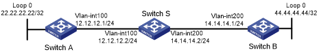
As shown in Figure 48, Switch S, Switch A, and Switch B belong to the same IS-IS routing domain.
Run IS-IS on all the switches to interconnect them with each other.
Enable IS-IS NSR on Switch S to ensure forwarding continuity between Switch A and Switch B when an active/standby switchover occurs on Switch S.
Figure 48: Network diagram
Configuration procedure
Configure the IP addresses and subnet masks for interfaces on the switches. (Details not shown.)
Configure IS-IS on the switches to make sure Switch S, Switch A, and Switch B can communicate with each other at Layer 3 and dynamic route update can be implemented among them with IS-IS. (Details not shown.)
Enable IS-IS NSR on Switch S.
<SwitchS> system-view
[SwitchS] isis 1
[SwitchS-isis-1] non-stop-routing
[SwitchS-isis-1] return
Verifying the configuration
# Reoptimize process placement on Switch S to trigger an active/standby switchover.
<SwitchS> system-view
[SwitchS] placement reoptimize
Predicted changes to the placement
Program                           Current location       New location
---------------------------------------------------------------------
syslog                            0/0                    0/0
diagusageratio                    0/0                    0/0
l3vpn                             0/0                    0/0
fc                                0/0                    0/0
dns                               0/0                    0/0
lauth                             0/0                    0/0
aaa                               0/0                    0/0
lsm                               0/0                    0/0
rm                                0/0                    0/0
rm6                               0/0                    0/0
track                             0/0                    0/0
ip6addr                           0/0                    0/0
ipaddr                            0/0                    0/0
rpm                               0/0                    0/0
trange                            0/0                    0/0
tunnel                            0/0                    0/0
lagg                              0/0                    0/0
bfd                               0/0                    0/0
acl                               0/0                    0/0
slsp                              0/0                    0/0
usr6                              0/0                    0/0
usr                               0/0                    0/0
qos                               0/0                    0/0
fczone                            0/0                    0/0
ethbase                           0/0                    0/0
ipcim                             0/0                    0/0
ip6base                           0/0                    0/0
ipbase                            0/0                    0/0
eth                               0/0                    0/0
eviisis                           0/0                    0/0
ifnet                             NA                     NA
isis                              0/0                    1/0
Continue? [y/n]:y
Re-optimization of the placement start. You will be notified on completion
Re-optimization of the placement complete. Use 'display placement' to view the new placement
# During the switchover period, display IS-IS neighbor information on Switch A to verify the neighborship between Switch A and Switch S.
<SwitchA> display isis peer

                         Peer information for IS-IS(1)
                         ----------------------------

 System Id: 0000.0000.0001
 Interface: vlan100                 Circuit Id: 0000.0000.0001.01
 State: Up     HoldTime:  25s       Type: L1(L1L2)     PRI: 64

 System Id: 0000.0000.0001
 Interface: vlan100                 Circuit Id: 0000.0000.0001.01
 State: Up     HoldTime:  27s       Type: L2(L1L2)     PRI: 64
# Display IS-IS routing information on Switch A to verify that Switch A has a route to the loopback interface of Switch B.
<SwitchA> display isis route

                         Route information for IS-IS(1)
                         -----------------------------

                         Level-1 IPv4 Forwarding Table
                         -----------------------------

 IPv4 Destination     IntCost    ExtCost ExitInterface   NextHop         Flags
-------------------------------------------------------------------------------
 12.12.12.0/24        10         NULL    vlan100         Direct          D/L/-
 22.22.22.22/32       10         NULL    Loop0           Direct          D/-/-
 14.14.14.0/32        10         NULL    vlan100         12.12.12.2      R/L/-
 44.44.44.44/32       10         NULL    vlan100         12.12.12.2      R/L/-

      Flags: D-Direct, R-Added to Rib, L-Advertised in LSPs, U-Up/Down Bit Set

                         Level-2 IPv4 Forwarding Table
                         -----------------------------

 IPv4 Destination     IntCost    ExtCost ExitInterface   NextHop         Flags
-------------------------------------------------------------------------------
 12.12.12.0/24        10         NULL    vlan100         Direct          D/L/-
 22.22.22.22/32       10         NULL    Loop0           Direct          D/-/-
 14.14.14.0/32        10         NULL
 44.44.44.44/32       10         NULL

      Flags: D-Direct, R-Added to Rib, L-Advertised in LSPs, U-Up/Down Bit Set
# Display IS-IS neighbor information on Switch B to verify the neighborship between Switch B and Switch S.
<SwitchB> display isis peer

                         Peer information for IS-IS(1)
                         ----------------------------

 System Id: 0000.0000.0001
 Interface: vlan200                 Circuit Id: 0000.0000.0001.01
 State: Up     HoldTime:  25s       Type: L1(L1L2)     PRI: 64

 System Id: 0000.0000.0001
 Interface: vlan200                 Circuit Id: 0000.0000.0001.01
 State: Up     HoldTime:  27s       Type: L2(L1L2)     PRI: 64
# Display IS-IS routing information on Switch B to verify that Switch B has a route to the loopback interface of Switch A.
<SwitchB> display isis route

                         Route information for IS-IS(1)
                         -----------------------------

                         Level-1 IPv4 Forwarding Table
                         -----------------------------

 IPv4 Destination     IntCost    ExtCost ExitInterface   NextHop         Flags
-------------------------------------------------------------------------------
 14.14.14.0/24        10         NULL    vlan200         Direct          D/L/-
 44.44.44.44/32       10         NULL    Loop0           Direct          D/-/-
 12.12.12.0/32        10         NULL    vlan200         14.14.14.4      R/L/-
 22.22.22.22/32       10         NULL    vlan200         14.14.14.4      R/L/-

      Flags: D-Direct, R-Added to Rib, L-Advertised in LSPs, U-Up/Down Bit Set

                         Level-2 IPv4 Forwarding Table
                         -----------------------------

 IPv4 Destination     IntCost    ExtCost ExitInterface   NextHop         Flags
-------------------------------------------------------------------------------
 14.14.14.0/24        10         NULL    vlan200         Direct          D/L/-
 44.44.44.44/32       10         NULL    Loop0           Direct          D/-/-
 12.12.12.0/32        10         NULL
 22.22.22.22/32       10         NULL

      Flags: D-Direct, R-Added to Rib, L-Advertised in LSPs, U-Up/Down Bit Set
The output shows that the neighbor information and routing information on Switch A and Switch B have not changed during the active/standby switchover on Switch S. The neighbors are unaware of the switchover.