IS-IS authentication configuration example
Network requirements
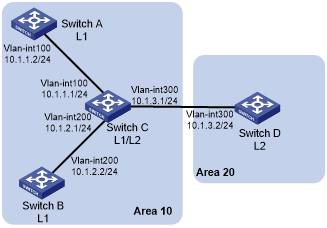
As shown in Figure 46, Switch A, Switch B, Switch C, and Switch D reside in the same IS-IS routing domain. Run IS-IS among them.
Switch A, Switch B, and Switch C belong to Area 10, and Switch D belongs to Area 20.
Configure neighbor relationship authentication between neighbors.
Configure area authentication in Area 10 to prevent untrusted routes from entering into the area.
Configure routing domain authentication on Switch C and Switch D to prevent untrusted routes from entering the routing domain.
Figure 46: Network diagram
Configuration procedure
Configure IP addresses for interfaces. (Details not shown.)
Configure basic IS-IS:
# Configure Switch A.
<SwitchA> system-view
[SwitchA] isis 1
[SwitchA-isis-1] network-entity 10.0000.0000.0001.00
[SwitchA-isis-1] quit
[SwitchA] interface vlan-interface 100
[SwitchA-Vlan-interface100] isis enable 1
[SwitchA-Vlan-interface100] quit
# Configure Switch B.
<SwitchB> system-view
[SwitchB] isis 1
[SwitchB-isis-1] network-entity 10.0000.0000.0002.00
[SwitchB-isis-1] quit
[SwitchB] interface vlan-interface 200
[SwitchB-Vlan-interface200] isis enable 1
[SwitchB-Vlan-interface200] quit
# Configure Switch C.
<SwitchC> system-view
[SwitchC] isis 1
[SwitchC-isis-1] network-entity 10.0000.0000.0003.00
[SwitchC-isis-1] quit
[SwitchC] interface vlan-interface 200
[SwitchC-Vlan-interface200] isis enable 1
[SwitchC-Vlan-interface200] quit
[SwitchC] interface vlan-interface 300
[SwitchC-Vlan-interface300] isis enable 1
[SwitchC-Vlan-interface300] quit
[SwitchC] interface vlan-interface 300
[SwitchC-Vlan-interface300] isis enable 1
[SwitchC-Vlan-interface300] quit
# Configure Switch D.
<SwitchD> system-view
[SwitchD] isis 1
[SwitchD-isis-1] network-entity 20.0000.0000.0001.00
[SwitchD-isis-1] quit
[SwitchD] interface vlan-interface 300
[SwitchD-Vlan-interface300] isis enable 1
[SwitchD-Vlan-interface300] quit
Configure neighbor relationship authentication between neighbors:
# Set the authentication mode to MD5 and set the plaintext key to eRq on VLAN-interface 100 of Switch A and on VLAN-interface 100 of Switch C.
[SwitchA] interface vlan-interface 100
[SwitchA-Vlan-interface100] isis authentication-mode md5 plain eRg
[SwitchA-Vlan-interface100] quit
[SwitchC] interface vlan-interface 100
[SwitchC-Vlan-interface100] isis authentication-mode md5 plain eRg
[SwitchC-Vlan-interface100] quit
# Set the authentication mode to MD5 and set the plaintext key to t5Hr on VLAN-interface 200 of Switch B and on VLAN-interface 200 of Switch C.
[SwitchB] interface vlan-interface 200
[SwitchB-Vlan-interface200] isis authentication-mode md5 plain t5Hr
[SwitchB-Vlan-interface200] quit
[SwitchC] interface vlan-interface 200
[SwitchC-Vlan-interface200] isis authentication-mode md5 plain t5Hr
[SwitchC-Vlan-interface200] quit
# Set the authentication mode to MD5 and set the plaintext key to hSec on VLAN-interface 300 of Switch D and on VLAN-interface 300 of Switch C.
[SwitchC] interface vlan-interface 300
[SwitchC-Vlan-interface300] isis authentication-mode md5 plain hSec
[SwitchC-Vlan-interface300] quit
[SwitchD] interface vlan-interface 300
[SwitchD-Vlan-interface300] isis authentication-mode md5 plain hSec
[SwitchD-Vlan-interface300] quit
Set the area authentication mode to MD5 and set the plaintext key to 10Sec on Switch A, Switch B, and Switch C.
[SwitchA] isis 1
[SwitchA-isis-1] area-authentication-mode md5 plain 10Sec
[SwitchA-isis-1] quit
[SwitchB] isis 1
[SwitchB-isis-1] area-authentication-mode md5 plain 10Sec
[SwitchB-isis-1] quit
[SwitchC] isis 1
[SwitchC-isis-1] area-authentication-mode md5 plain 10Sec
[SwitchC-isis-1] quit
Set routing domain authentication mode to MD5 and set the plaintext key to 1020Sec on Switch C and Switch D.
[SwitchC] isis 1
[SwitchC-isis-1] domain-authentication-mode md5 plain 1020Sec
[SwitchC-isis-1] quit
[SwitchD] isis 1
[SwitchD-isis-1] domain-authentication-mode md5 plain 1020Sec