Basic IS-IS configuration example
Network requirements
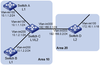
As shown in Figure 43, Switch A, Switch B, Switch C, and Switch D reside in an IS-IS AS.
Switch A and B are Level-1 switches, Switch D is a Level-2 switch, and Switch C is a Level-1-2 switch. Switch A, Switch B, and Switch C are in Area 10, and Switch D is in Area 20.
Figure 43: Network diagram
Configuration procedure
Configure IP addresses for interfaces. (Details not shown.)
Configure IS-IS:
# Configure Switch A.
<SwitchA> system-view
[SwitchA] isis 1
[SwitchA-isis-1] is-level level-1
[SwitchA-isis-1] network-entity 10.0000.0000.0001.00
[SwitchA-isis-1] quit
[SwitchA] interface vlan-interface 100
[SwitchA-Vlan-interface100] isis enable 1
[SwitchA-Vlan-interface100] quit
# Configure Switch B.
<SwitchB> system-view
[SwitchB] isis 1
[SwitchB-isis-1] is-level level-1
[SwitchB-isis-1] network-entity 10.0000.0000.0002.00
[SwitchB-isis-1] quit
[SwitchB] interface vlan-interface 200
[SwitchB-Vlan-interface200] isis enable 1
[SwitchB-Vlan-interface200] quit
# Configure Switch C.
<SwitchC> system-view
[SwitchC] isis 1
[SwitchC-isis-1] network-entity 10.0000.0000.0003.00
[SwitchC-isis-1] quit
[SwitchC] interface vlan-interface 100
[SwitchC-Vlan-interface100] isis enable 1
[SwitchC-Vlan-interface100] quit
[SwitchC] interface vlan-interface 200
[SwitchC-Vlan-interface200] isis enable 1
[SwitchC-Vlan-interface200] quit
[SwitchC] interface vlan-interface 300
[SwitchC-Vlan-interface300] isis enable 1
[SwitchC-Vlan-interface300] quit
# Configure Switch D.
<SwitchD> system-view
[SwitchD] isis 1
[SwitchD-isis-1] is-level level-2
[SwitchD-isis-1] network-entity 20.0000.0000.0004.00
[SwitchD-isis-1] quit
[SwitchD] interface vlan-interface 100
[SwitchD-Vlan-interface100] isis enable 1
[SwitchD-Vlan-interface100] quit
[SwitchD] interface vlan-interface 300
[SwitchD-Vlan-interface300] isis enable 1
[SwitchD-Vlan-interface300] quit
Verifying the configuration
# Display the IS-IS LSDB on each switch to verify the LSPs.
[SwitchA] display isis lsdb

                       Database information for IS-IS(1)
                       ---------------------------------

                          Level-1 Link State Database
                          ---------------------------

LSPID                 Seq Num      Checksum   Holdtime   Length  ATT/P/OL
--------------------------------------------------------------------------
0000.0000.0001.00-00* 0x00000004   0xdf5e     1096       68      0/0/0
0000.0000.0002.00-00  0x00000004   0xee4d     1102       68      0/0/0
0000.0000.0002.01-00  0x00000001   0xdaaf     1102       55      0/0/0
0000.0000.0003.00-00  0x00000009   0xcaa3     1161       111     1/0/0
0000.0000.0003.01-00  0x00000001   0xadda     1112       55      0/0/0

    *-Self LSP, +-Self LSP(Extended), ATT-Attached, P-Partition, OL-Overload
[SwitchB] display isis lsdb

                       Database information for IS-IS(1)
                       ---------------------------------

                          Level-1 Link State Database
                          ---------------------------

LSPID                 Seq Num      Checksum   Holdtime    Length  ATT/P/OL
--------------------------------------------------------------------------
0000.0000.0001.00-00  0x00000006   0xdb60     988         68      0/0/0
0000.0000.0002.00-00* 0x00000008   0xe651     1189        68      0/0/0
0000.0000.0002.01-00* 0x00000005   0xd2b3     1188        55      0/0/0
0000.0000.0003.00-00  0x00000014   0x194a     1190        111     1/0/0
0000.0000.0003.01-00  0x00000002   0xabdb     995         55      0/0/0

    *-Self LSP, +-Self LSP(Extended), ATT-Attached, P-Partition, OL-Overload
[SwitchC] display isis lsdb

                       Database information for IS-IS(1)
                       ---------------------------------

                          Level-1 Link State Database
                          ---------------------------

LSPID                 Seq Num      Checksum   Holdtime    Length  ATT/P/OL
--------------------------------------------------------------------------
0000.0000.0001.00-00  0x00000006   0xdb60     847         68      0/0/0
0000.0000.0002.00-00  0x00000008   0xe651     1053        68      0/0/0
0000.0000.0002.01-00  0x00000005   0xd2b3     1052        55      0/0/0
0000.0000.0003.00-00* 0x00000014   0x194a     1051        111     1/0/0
0000.0000.0003.01-00* 0x00000002   0xabdb     854         55      0/0/0

    *-Self LSP, +-Self LSP(Extended), ATT-Attached, P-Partition, OL-Overload

                          Level-2 Link State Database
                          ---------------------------

LSPID                 Seq Num      Checksum   Holdtime    Length  ATT/P/OL
--------------------------------------------------------------------------
0000.0000.0003.00-00* 0x00000012   0xc93c     842         100     0/0/0
0000.0000.0004.00-00  0x00000026   0x331      1173        84      0/0/0
0000.0000.0004.01-00  0x00000001   0xee95     668         55      0/0/0

    *-Self LSP, +-Self LSP(Extended), ATT-Attached, P-Partition, OL-Overload
[SwitchD] display isis lsdb

                       Database information for IS-IS(1)
                       ---------------------------------

                          Level-2 Link State Database
                          ---------------------------

LSPID                 Seq Num      Checksum      Holdtime      Length  ATT/P/OL
-------------------------------------------------------------------------------
0000.0000.0003.00-00  0x00000013   0xc73d        1003          100     0/0/0
0000.0000.0004.00-00* 0x0000003c   0xd647        1194          84      0/0/0
0000.0000.0004.01-00* 0x00000002   0xec96        1007          55      0/0/0

    *-Self LSP, +-Self LSP(Extended), ATT-Attached, P-Partition, OL-Overload
# Display the IS-IS routing information on each switch.
[SwitchA] display isis route

                         Route information for IS-IS(1)
                         ------------------------------

                         Level-1 IPv4 Forwarding Table
                         -----------------------------

 IPv4 Destination     IntCost    ExtCost ExitInterface   NextHop         Flags
-------------------------------------------------------------------------------
 10.1.1.0/24          10         NULL    Vlan100         Direct          D/L/-
 10.1.2.0/24          20         NULL    Vlan100         10.1.1.1        R/-/-
 192.168.0.0/24       20         NULL    Vlan100         10.1.1.1        R/-/-
 0.0.0.0/0            10         NULL    Vlan100         10.1.1.1        R/-/-

      Flags: D-Direct, R-Added to Rib, L-Advertised in LSPs, U-Up/Down Bit Set
[SwitchC] display isis route

                         Route information for IS-IS(1)
                         ------------------------------

                         Level-1 IPv4 Forwarding Table
                         -----------------------------

 IPv4 Destination     IntCost    ExtCost ExitInterface   NextHop         Flags
-------------------------------------------------------------------------------
 192.168.0.0/24       10         NULL    Vlan300         Direct          D/L/-
 10.1.1.0/24          10         NULL    Vlan100         Direct          D/L/-
 10.1.2.0/24          10         NULL    Vlan200         Direct          D/L/-

      Flags: D-Direct, R-Added to Rib, L-Advertised in LSPs, U-Up/Down Bit Set

                         Level-2 IPv4 Forwarding Table
                         -----------------------------

 IPv4 Destination     IntCost    ExtCost ExitInterface   NextHop         Flags
-------------------------------------------------------------------------------
 192.168.0.0/24       10         NULL                                    D/L/-
 10.1.1.0/24          10         NULL                                    D/L/-
 10.1.2.0/24          10         NULL                                    D/L/-
 172.16.0.0/16        20         NULL    Vlan300         192.168.0.2     R/-/-

      Flags: D-Direct, R-Added to Rib, L-Advertised in LSPs, U-Up/Down Bit Set
[SwitchD] display isis route

                         Route information for IS-IS(1)
                         ------------------------------

                         Level-2 IPv4 Forwarding Table
                         -----------------------------

 IPv4 Destination     IntCost    ExtCost ExitInterface   NextHop         Flags
-------------------------------------------------------------------------------
 192.168.0.0/24       10         NULL    Vlan300         Direct          D/L/-
 10.1.1.0/24          20         NULL    Vlan300         192.168.0.1     R/-/-
 10.1.2.0/24          20         NULL    Vlan300         192.168.0.1     R/-/-
 172.16.0.0/16        10         NULL    Vlan100         Direct          D/L/-

      Flags: D-Direct, R-Added to Rib, L-Advertised in LSPs, U-Up/Down Bit Set
The output shows that the routing table of Level-1 switches contains a default route with the next hop as the Level-1-2 switch. The routing table of Level-2 switch contains both routing information of Level-1 and Level-2.