Configuring RIP FRR
Network requirements
As shown in Figure 16, Switch A, Switch B, and Switch C run RIPv2. Configure RIP FRR so that when Link A becomes unidirectional, services can be switched to Link B immediately.
Figure 16: Network diagram
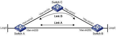
Table 8: Interface and IP address assignment
Device | Interface | IP address |
|---|---|---|
Switch A | VLAN-interface 100 | 12.12.12.1/24 |
Switch A | VLAN-interface 200 | 13.13.13.1/24 |
Switch A | Loopback 0 | 1.1.1.1/32 |
Switch B | VLAN-interface 101 | 24.24.24.4/24 |
Switch B | VLAN-interface 200 | 13.13.13.2/24 |
Switch B | Loopback 0 | 4.4.4.4/32 |
Switch C | VLAN-interface 100 | 12.12.12.2/24 |
Switch C | VLAN-interface 101 | 24.24.24.2/24 |
Configuration procedure
Configure IP addresses and subnet masks for interfaces on the switches. (Details not shown.)
Configure RIPv2 on the switches to make sure Switch A, Switch B, and Switch C can communicate with each other at Layer 3. (Details not shown.)
Configure RIP FRR:
# Configure Switch A.
<SwitchA> system-view
[SwitchA] ip prefix-list abc index 10 permit 4.4.4.4 32
[SwitchA] route-policy frr permit node 10
[SwitchA-route-policy-frr-10] if-match ip address prefix-list abc
[SwitchA-route-policy-frr-10] apply fast-reroute backup-interface vlan-interface 100 backup-nexthop 12.12.12.2
[SwitchA-route-policy-frr-10] quit
[SwitchA] rip 1
[SwitchA-rip-1] fast-reroute route-policy frr
[SwitchA-rip-1] quit
# Configure Switch B.
<SwitchB> system-view
[SwitchB] ip prefix-list abc index 10 permit 1.1.1.1 32
[SwitchB] route-policy frr permit node 10
[SwitchB-route-policy-frr-10] if-match ip address prefix-list abc
[SwitchB-route-policy-frr-10] apply fast-reroute backup-interface vlan-interface 101 backup-nexthop 24.24.24.2
[SwitchB-route-policy-frr-10] quit
[SwitchB] rip 1
[SwitchB-rip-1] fast-reroute route-policy frr
[SwitchB-rip-1] quit
Verifying the configuration
# Display route 4.4.4.4/32 on Switch A to view the backup next hop information.
[SwitchA] display ip routing-table 4.4.4.4 verbose

Summary Count : 1

Destination: 4.4.4.4/32
   Protocol: RIP
 Process ID: 1
  SubProtID: 0x1                     Age: 04h20m37s
       Cost: 1                Preference: 100
      IpPre: N/A              QosLocalID: N/A
        Tag: 0                     State: Active Adv
  OrigTblID: 0x0                 OrigVrf: default-vrf
    TableID: 0x2                  OrigAs: 0
      NibID: 0x26000002           LastAs: 0
     AttrID: 0xffffffff         Neighbor: 13.13.13.2
      Flags: 0x1008c         OrigNextHop: 13.13.13.2
      Label: NULL            RealNextHop: 13.13.13.2
    BkLabel: NULL              BkNextHop: 12.12.12.2
  Tunnel ID: Invalid           Interface: Vlan-interface200
BkTunnel ID: Invalid         BkInterface: Vlan-interface100
   FtnIndex: 0x0            TrafficIndex: N/A
  Connector: N/A
# Display route 1.1.1.1/32 on Switch B to view the backup next hop information.
[SwitchB] display ip routing-table 1.1.1.1 verbose

Summary Count : 1

Destination: 1.1.1.1/32
   Protocol: RIP
 Process ID: 1
  SubProtID: 0x1                     Age: 04h20m37s
       Cost: 1                Preference: 100
      IpPre: N/A              QosLocalID: N/A
        Tag: 0                     State: Active Adv
  OrigTblID: 0x0                 OrigVrf: default-vrf
    TableID: 0x2                  OrigAs: 0
      NibID: 0x26000002           LastAs: 0
     AttrID: 0xffffffff         Neighbor: 13.13.13.1
      Flags: 0x1008c         OrigNextHop: 13.13.13.1
      Label: NULL            RealNextHop: 13.13.13.1
    BkLabel: NULL              BkNextHop: 24.24.24.2
  Tunnel ID: Invalid           Interface: Vlan-interface200
BkTunnel ID: Invalid         BkInterface: Vlan-interface101
   FtnIndex: 0x0            TrafficIndex: N/A
  Connector: N/A