Configuring basic RIP
Network requirements
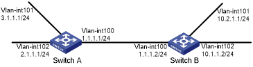
As shown in Figure 7, enable RIPv2 on all interfaces on Switch A and Switch B. Configure Switch B to not advertise route 10.2.1.0/24 to Switch A, and to accept only route 2.1.1.0/24 from Switch A.
Figure 7: Network diagram
Configuration procedure
Configure IP addresses for interfaces. (Details not shown.)
Configure basic RIP by using either of the following methods:
(Method 1) # Enable RIP on the specified networks on Switch A.
<SwitchA> system-view
[SwitchA] rip
[SwitchA-rip-1] network 1.0.0.0
[SwitchA-rip-1] network 2.0.0.0
[SwitchA-rip-1] network 3.0.0.0
[SwitchA-rip-1] quit
(Method 2) # Enable RIP on the specified interfaces on Switch B.
<SwitchB> system-view
[SwitchB] rip
[SwitchB-rip-1] quit
[SwitchB] interface vlan-interface 100
[SwitchB-Vlan-interface100] rip 1 enable
[SwitchB-Vlan-interface100] quit
[SwitchB] interface vlan-interface 101
[SwitchB-Vlan-interface101] rip 1 enable
[SwitchB-Vlan-interface101] quit
[SwitchB] interface vlan-interface 102
[SwitchB-Vlan-interface102] rip 1 enable
[SwitchB-Vlan-interface102] quit
# Display the RIP routing table of Switch A.
[SwitchA] display rip 1 route
 Route Flags: R - RIP, T - TRIP
              P - Permanent, A - Aging, S - Suppressed, G - Garbage-collect
              D - Direct, O - Optimal, F - Flush to RIB
----------------------------------------------------------------------------
 Peer 1.1.1.2 on Vlan-interface100
      Destination/Mask        Nexthop           Cost    Tag     Flags   Sec
      10.0.0.0/8              1.1.1.2           1       0       RAOF    11
 Local route
      Destination/Mask        Nexthop           Cost    Tag     Flags   Sec
      1.1.1.0/24              0.0.0.0           0       0       RDOF    -
      2.1.1.0/24              0.0.0.0           0       0       RDOF    -
      3.1.1.0/24              0.0.0.0           0       0       RDOF    -
The output shows that RIPv1 uses a natural mask.
Configure a RIP version:
# Configure RIPv2 on Switch A.
[SwitchA] rip
[SwitchA-rip-1] version 2
[SwitchA-rip-1] undo summary
[SwitchA-rip-1] quit
# Configure RIPv2 on Switch B.
[SwitchB] rip
[SwitchB-rip-1] version 2
[SwitchB-rip-1] undo summary
[SwitchB-rip-1] quit
# Display the RIP routing table on Switch A.
[SwitchA] display rip 1 route
 Route Flags: R - RIP, T - TRIP
              P - Permanent, A - Aging, S - Suppressed, G - Garbage-collect
              D - Direct, O - Optimal, F - Flush to RIB
----------------------------------------------------------------------------

 Peer 1.1.1.2 on Vlan-interface100
      Destination/Mask        Nexthop           Cost    Tag     Flags   Sec
      10.0.0.0/8              1.1.1.2           1       0       RAOF    50
      10.2.1.0/24             1.1.1.2           1       0       RAOF    16
      10.1.1.0/24             1.1.1.2           1       0       RAOF    16
 Local route
      Destination/Mask        Nexthop           Cost    Tag     Flags   Sec
      1.1.1.0/24              0.0.0.0           0       0       RDOF    -
      2.1.1.0/24              0.0.0.0           0       0       RDOF    -
      3.1.1.0/24              0.0.0.0           0       0       RDOF    -
The output shows that RIPv2 uses classless subnet masks.
![[NOTE: ]](images/note.png)
NOTE:
After RIPv2 is configured, RIPv1 routes might still exist in the routing table until they are aged out.
# Display the RIP routing table on Switch B.
[SwitchB] display rip 1 route
 Route Flags: R - RIP, T - TRIP
              P - Permanent, A - Aging, S - Suppressed, G - Garbage-collect
              D - Direct, O - Optimal, F - Flush to RIB
----------------------------------------------------------------------------
 Peer 1.1.1.1 on Vlan-interface100
      Destination/Mask        Nexthop           Cost    Tag     Flags   Sec
      2.1.1.0/24              192.168.1.3       1       0       RAOF    19
      3.1.1.0/24              192.168.1.3       1       0       RAOF    19
 Local route
      Destination/Mask        Nexthop           Cost    Tag     Flags   Sec
      1.1.1.0/24              0.0.0.0           0       0       RDOF    -
      10.1.1.0/24             0.0.0.0           0       0       RDOF    -
      10.2.1.0/24             0.0.0.0           0       0       RDOF    -
Configure route filtering:
# Reference IP prefix lists on Switch B to filter received and redistributed routes.
[SwitchB] ip prefix-list aaa index 10 permit 2.1.1.0 24
[SwitchB] ip prefix-list bbb index 10 deny 10.2.1.0 24
[SwitchB] ip prefix-list bbb index 11 permit 0.0.0.0 0 less-equal 32
[SwitchB] rip 1
[SwitchB-rip-1] filter-policy prefix-list aaa import
[SwitchB-rip-1] filter-policy prefix-list bbb export
[SwitchB-rip-1] quit
# Display the RIP routing table on Switch A.
[SwitchA] display rip 100 route
 Route Flags: R - RIP, T - TRIP
              P - Permanent, A - Aging, S - Suppressed, G - Garbage-collect
----------------------------------------------------------------------------
 Peer 1.1.1.2 on Vlan-interface100
      Destination/Mask        Nexthop           Cost    Tag     Flags   Sec
      10.1.1.0/24             1.1.1.2           1       0       RAOF    19
 Local route
      Destination/Mask        Nexthop           Cost    Tag     Flags   Sec
      1.1.1.0/24              0.0.0.0           0       0       RDOF    -
      2.1.1.0/24              0.0.0.0           0       0       RDOF    -
      3.1.1.0/24              0.0.0.0           0       0       RDOF    -
# Display the RIP routing table on Switch B.
[SwitchB] display rip 1 route
 Route Flags: R - RIP, T - TRIP
              P - Permanent, A - Aging, S - Suppressed, G - Garbage-collect
              D - Direct, O - Optimal, F - Flush to RIB
----------------------------------------------------------------------------
 Peer 1.1.1.1 on Vlan-interface100
      Destination/Mask        Nexthop           Cost    Tag     Flags   Sec
      2.1.1.0/24              1.1.1.3           1       0       RAOF    19
 Local route
      Destination/Mask        Nexthop           Cost    Tag     Flags   Sec
      1.1.1.0/24              0.0.0.0           0       0       RDOF    -
      10.1.1.0/24             0.0.0.0           0       0       RDOF    -
      10.2.1.0/24             0.0.0.0           0       0       RDOF    -