L2TP tunneling modes and tunnel establishment process
L2TP tunneling modes include NAS-initiated, client-initiated, and LAC-auto-initiated.
NAS-initiated tunneling mode
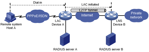
As shown in Figure 23, a remote system dials in to the LAC through a PPPoE/ISDN network. The LAC initiates a tunneling request to the LNS over the Internet.
Figure 23: NAS-initiated tunneling mode
A NAS-initiated tunnel has the following characteristics:
The remote system only needs to support PPP, and it does not need to support L2TP.
Authentication and accounting of the remote system can be implemented on the LAC or LNS.
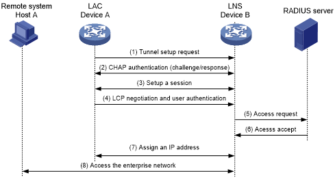
Figure 24: NAS-initiated tunnel establishment process
As shown in Figure 24, the following workflow is used to establish a NAS-initiated tunnel:
A remote system (Host A) initiates a PPP connection to the LAC (Device A).
The remote system and LAC perform PPP LCP negotiation.
The LAC authenticates PPP user information of Host A by using PAP or CHAP.
The LAC sends the authentication information (username and password) to its RADIUS server (RADIUS server A) for authentication.
RADIUS server A authenticates the user and returns the result.
The LAC initiates an L2TP tunneling request to the LNS (Device B) when the following conditions exist:
The user passes the authentication.
The user is determined to be an L2TP user according to the username or the ISP domain to which the user belongs.
If tunnel authentication is needed, the LAC and LNS send CHAP challenge messages to authenticate each other before successfully establishing an L2TP tunnel.
The LAC and LNS negotiate to establish L2TP sessions.
The LAC sends PPP user information and PPP negotiation parameters to the LNS.
The LNS sends the authentication information to its RADIUS server (RADIUS server B) for authentication.
RADIUS server B authenticates the user and returns the result.
If the user passes the authentication, the LNS assigns a private IP address to the remote system (Host A).
The PPP user can access internal resources of the enterprise.
In steps 12 and 13, the LAC forwards packets for the remote system and LNS. Host A and LAC exchange PPP frames, and the LAC and LNS exchange L2TP packets.
Client-initiated tunneling mode
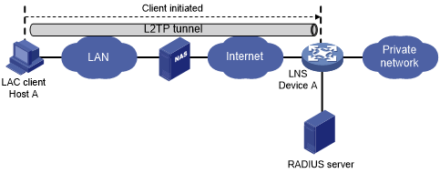
As shown in Figure 25, a remote system running L2TP (LAC client) has a public IP address to communicate with the LNS through the Internet. The LAC client can directly initiate a tunneling request to the LNS without any dedicated LAC devices.
Figure 25: Client-initiated tunneling mode
A client-initiated tunnel has the following characteristics:
A client-initiated tunnel has higher security because it is established between a remote system and the LNS.
The remote system must support L2TP and be able to communicate with the LNS. This causes poor expandability.
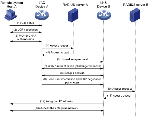
As shown in Figure 26, the workflow for establishing a client-initiated tunnel is similar to that for establishing a NAS-initiated tunnel. (Details not shown.)
Figure 26: Client-initiated tunnel establishment process
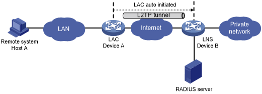
LAC-auto-initiated tunneling mode
In NAS-initiated mode, a remote system must successfully dial in to the LAC through PPPoE or ISDN.
In LAC-auto-initiated mode, you can use the l2tp-auto-client command on the LAC to trigger the LAC to initiate a tunneling request to the LNS. When a remote system accesses the private network, the LAC forwards data through the L2TP tunnel.
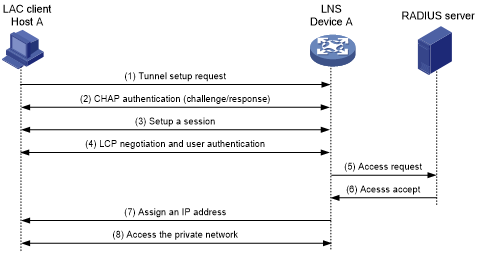
Figure 27: LAC-auto-initiated tunneling mode
An LAC-auto-initiated tunnel has the following characteristics:
The connection between a remote system and the LAC is not confined to a dial-up connection and can be any IP-based connection.
An L2TP session is established immediately after an L2TP tunnel is established. Then, the LAC and LNS, acting as the PPPoE client and PPPoE server, respectively, perform PPP negotiation.
An L2TP tunnel can carry only one L2TP session.
The LNS assigns a private IP address to the LAC instead of to the remote system.
As shown in Figure 28, the workflow for establishing an LAC-auto-initiated tunnel is similar to that for establishing a NAS-initiated tunnel. (Details not shown.)
Figure 28: Establishment process for LAC-auto-initiated tunnels