Introduction to R2 signaling
ITU-T recommendations Q.400 through Q.490 define the R2 signaling standards. However, the R2 signaling standards implemented in different countries and regions are ITU variants.
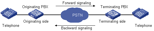
R2 signaling includes two categories: digital line signaling and interregister signaling. Digital line signaling conveys status information about E1 trunks to describe whether the trunks are occupied, released, or blocked. Interregister signaling transmits such information as address in multi-frequency compelled approach. Generally, the calling side serves as the originating PBX and the called side serves as the terminating PBX. Signals sent by the originating PBX are called forward signals and those sent by the terminating PBX are called backward signals, as shown in Figure 18.
Figure 18: R2 signaling elements
ITU-T digital line signaling
Digital line signaling is responsible for changing call statuses and conditions of a line. It functions to identify and detect these four states: calling party goes off-hook and seizes the line, called party goes off-hook and answers the call, calling party releases the call, and called party releases the call. Accordingly, it sets the line to be idle or seized. This signaling is transmitted in the 16th multiframe timeslot of PCM system. The two transmission directions of each line have 4 bits (A, B, C and D) as flag bits, with C and D bits fixed to 01. Therefore, the forward line signaling adopts af and bf bits and the backward line signaling adopts ab and bb bits, as shown in the following table:
Table 5: Line signaling bit description
Bit | Description | Vale = 0 | Value = 1 |
|---|---|---|---|
af | Identifies working state of device at the originating side and indicates state of the calling party line. | Off-hook, seized | On-hook (idle) |
bf | Indicates fault state from the originating side to the terminating side. | Normal | Faulty |
ab | Indicates state of the called party line (on-hook or off-hook). | Off-hook by called party | On-hook by called party |
bb | Indicates state of device at the terminating side (idle or seized). | Idle | Seized or blocked |
Table 6: State code of line signaling
State of the circuit | Signaling code | |||
|---|---|---|---|---|
Forward | Backward | |||
af | bf | ab | bb | |
Idle | 1 | 0 | 1 | 0 |
Seized | 0 | 0 | 1 | 0 |
Seizure-ack | 0 | 0 | 1 | 1 |
Answer | 0 | 0 | 0 | 1 |
Clear-back | 0 | 0 | 1 | 1 |
Clear-forward | 0 | 0 | 0/1 | 1 |
Blocked | 1 | 0 | 1 | 1 |
Unblocked | 1 | 0 | 1 | 0 |
The following are typical R2 digital line signaling interaction procedures:
Call establishment.
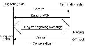
When the circuit is idle, the originating side sends a forward seizure signal to the terminating side. The terminating side then sends back a seizure acknowledgement signal after it recognizes the seizure signal. At this time, the circuits of the both sides are seized, and they start interregister signaling exchange. When the called party picks up the phone, the terminating side sends a backward answer signal. After the originating side recognizes the received signal, it establishes the call.
Figure 19: R2 digital line signaling – call establishment
Originating side releases the call.
The originating side sends a clear-forward signal 10. When the terminating side recognizes the clear-forward signal, it sends a backward signal 10 (release guard signal or clear-forward acknowledgement signal). After the originating side recognizes the backward signal 10, it releases the circuit.
Figure 20: R2 digital line signaling – originating side releases the call
Terminating side releases the call.
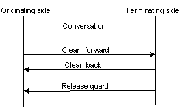
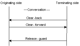
The terminating side sends a clear-back signal 11. After the originating side receives the clear-back signal, it sends a clear-forward signal 10. After the terminating side recognizes the forward signal 10 sent by the originating side, it sends a backward signal 10. After the originating side recognizes the backward signal 10, it releases the circuit.
Figure 21: R2 digital line signaling – terminating side releases the call
Line released by forced release signal.
When the terminating side supports metering signals, the system might send a forced release signal 00 instead of a clear-back signal 11 to release the line. This is to avoid collision between the clear-back signal sent by the called party and the metering signal.
Blocking in idle state or during conversation.
After the originating side receives a blocking signal 11 from the terminating side when the circuit is idle or during conversation, it sends a forward signal 10. At this time, the circuit is blocked. When the terminating side unblocks the circuit, it sends a backward signal 10 in the corresponding line to indicate that the line is idle. The originating side should maintain the forward signal 10 and unblock the local-end circuit for next call.
Troubleshooting in idle state.
If the terminating side receives a forward signal 11 from the originating side to indicate a device fault when the circuit is idle, the terminating side sends a backward signal 11. Then, the circuit is in faulty state. When the device recovers, the originating side sends the forward signal 10, and the terminating side responds with the signal 10. At this time the circuit regains normal state.
Troubleshooting during conversation.
After the terminating side receives a forward signal 11 from the originating side to indicate device fault during conversation, the terminating side releases the line backward. At the same time, it sends a backward signal 11. Then, the circuit is in faulty state. When the device recovers, the originating side sends a forward signal 10, and the terminating side sends back a signal 10. At this time, the circuit recovers.
ITU-T interregister signaling
Interregister signaling controls automatic connection of circuits. It adopts MFC mode and includes forward signaling and backward signaling. Forward signaling exchange includes Group I and Group II, while backward signaling exchange includes Group A and Group B. When the originating side recognizes the seizure acknowledgement signal, the register begins to send the first digit of the called number, and waits for the response of Group A signaling from the terminating side.
Group I forward signals—Include connection control signals and digit signals.
Table 7: Forward Group I signals
Designation | Basic meaning |
|---|---|
I-1 through I-10 | Digits 1, 2, 3, 4, 5, 6, 7, 8, 9, and 0, responsible for sending number information to the terminating side |
I-11 | Spare for national use |
I-12 | Request refused |
I-13 | Connected to tested device |
I-14 | Spare for national use |
I-15 | Address identification terminator and pulse terminator (used in international calls) |
Group A backward signals—Control signals used for controlling and acknowledging Group I forward signals.
Table 8: Group A backward signals
Designation | Basic Meaning |
|---|---|
A-1 | Send next digit |
A-2 | Send last but one digit |
A-3 | Address-complete; changeover to reception of Group B signals |
A-4 | Congestion in the national network; terminate interregister signaling exchange |
A-5 | Send calling party’s category |
A-6 | Address-complete; terminate interregister signaling exchange, charge, and set up speech conditions |
A-7 | Send last but two digits |
A-8 | Send last but three digits |
A-9 | Spare for national use |
A-10 | Spare for national use |
A-11 | Send country code indicator |
A-12 | Send language or discrimination digit |
A-13 | Send nature of circuit |
A-14 | Request for information on use of an echo canceller |
A-15 | Congestion in an international exchange; terminate interregister signaling interaction |
Group II forward signals—Identify the calling party category. The system looks at the calling party category to decide whether the calling party can perform forced release or break-in.
Table 9: Group II forward signals
Designation | Basic Meaning |
|---|---|
II-1 | Subscriber without priority |
II-2 | Subscriber with priority |
II-3 | Maintenance equipment |
II-4 | Spare for national use |
II-5 | Operator |
II-6 | Data transmission |
II-7 | Subscriber (or operator without forward transfer facility), for international use |
II-8 | Data transmission (for international use) |
II-9 | Subscriber with priority (for international use) |
II-10 | Operator with forward transfer facility (for international aid use) |
II-11 through II-15 | Spare for national use |
Group B backward signals—Identify the state of the called party, and acknowledge Group II signals and control connection.
Table 10: Group B backward signals
Designation | Basic Meaning |
|---|---|
B-1 | Spare for national use |
B-2 | Send special information tone |
B-3 | Subscriber line busy |
B-4 | Congestion |
B-5 | Unallocated number |
B-6 | Subscriber line free, charge |
B-7 | Subscriber line free, no charge |
B-8 | Subscriber line out of order |
B-9 through B-15 | Spare for national use |
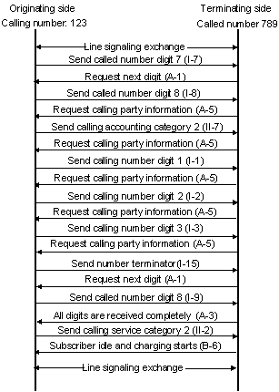
The following figure shows the exchange process requesting calling party information, which is typical of R2 interregister signaling.
Figure 22: ITU-T R2 interregister signaling exchange process