X2T PVC configuration example
Network requirements
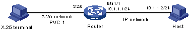
As shown in Figure 151, the router connects X.25 and IP networks together.
In this connection, the X.25 terminal communicates with the router through PVC and the X2T technology applied on the router enables the communication between the IP host and the X.25 terminal.
Figure 151: Network diagram
Configuration procedure
# Enable X.25 switching.
<Router> system-view
[Router] x25 switching
# Configure interface Serial 2/0.
[Router] interface serial 2/0
[Router-Serial2/0] link-protocol x25 dce
[Router-Serial2/0] x25 vc-range in-channel 10 20 bi-channel 30 1024
[Router-Serial2/0] quit
# Configure interface Ethernet 1/1.
[Router] interface ethernet 1/1
[Router-Ethernet1/1] ip address 10.1.1.1 255.255.255.0
[Router-Ethernet1/1] quit
# Configure an X2T route.
[Router] translate ip 10.1.1.1 port 102 pvc serial2/0 1