Transmitting IP datagrams through X.25 PVCs
Network requirements
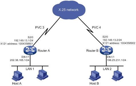
As shown in Figure 139,
The PVC range that the packet network allows is [1, 8]. The PVC numbers assigned to Router A and Router B are 3 and 4.
The IP addresses of LAN 1 and LAN 2 are 202.38.165.0/24 and 196.25.231.0/24.
Exchange route information between LAN 1 and LAN 2 by using RIP, so that Host A and Host B can exchange information without any static route.
Figure 139: Network diagram
Configuration procedure
Configure Router A:
# Configure interface Ethernet 1/1.
<RouterA> system-view
[RouterA] interface ethernet 1/1
[RouterA-Ethernet1/1] ip address 202.38.165.1 255.255.255.0
[RouterA-Ethernet1/1] quit
# Configure interface Serial 2/0.
[RouterA] interface serial 2/0
[RouterA-Serial2/0] ip address 192.149.13.1 255.255.255.0
[RouterA-Serial2/0] link-protocol x25
[RouterA-Serial2/0] x25 x121-address 1004358901
[RouterA-Serial2/0] x25 vc-range bi-channel 9 1024
[RouterA-Serial2/0] x25 pvc 3 ip 192.149.13.2 x121-address 1004358902 broadcast packet-size 512 512 window-size 5 5
[RouterA-Serial2/0] shutdown
[RouterA-Serial2/0] undo shutdown
[RouterA-Serial2/0] quit
# Enable RIP.
[RouterA] rip
[RouterA-rip-1] network 192.0.0.0
[RouterA-rip-1] network 202.0.0.0
Configure Router B:
# Configure interface Ethernet 1/1.
<RouterB> system-view
[RouterB] interface ethernet 1/1
[RouterB-Ethernet1/1] ip address 196.25.231.1 255.255.255.0
[RouterB-Ethernet1/1] quit
# Configure interface Serial 2/0.
[RouterB] interface serial 2/0
[RouterB-Serial2/0] ip address 192.149.13.2 255.255.255.0
[RouterB-Serial2/0] link-protocol x25
[RouterB-Serial2/0] x25 x121-address 1004358902
[RouterB-Serial2/0] x25 vc-range bi-channel 8 1024
[RouterB-Serial2/0] x25 pvc 4 ip 192.149.13.1 x121-address 1004358901 broadcast packet-size 512 512 window-size 5 5
[RouterB-Serial2/0] shutdown
[RouterB-Serial2/0] undo shutdown
[RouterB-Serial2/0] quit
# Enable RIP.
[RouterB] rip
[RouterB-rip-1] network 192.0.0.0
[RouterB-rip-1] network 196.0.0.0
Distinguish between virtual circuits and logical channels as follows:
A virtual circuit refers to the end-to-end logical link between the calling DTE and the called DTE.
A logical channel refers to the logical link between two directly connected devices (either between DTE and DCE, or between the ports of two PSEs).
A virtual circuit consists of several logical channels, and each logical channel has a separate number. A virtual circuit between Router A and Router B can be the one shown in Figure 140 (suppose this virtual circuit passes four packet switches in the network).
Figure 140: One virtual circuit consisting of several logical channels
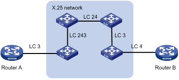
The PVC 3 and PVC 4 mentioned in the example refer to the numbers of the logical channels between the routers and the PBXs directly connected. The two sides of the PVC can identify the same PVC by using their logical channel numbers, however, without the likelihood of causing any mistake. This is why no strict distinction is made between "virtual circuit" and "logical channel."
Verifying the configuration
Ping Router B from Router A to verify Router A can reach Router B.
# Display the X.25 address mapping table on Router A.
[RouterA] display x25 map
  Interface: Serial2/0(protocol status is UP)
    ip 192.149.13.2  X.121 address:1004358902
      Map-type: PVC_MAP  VC-number: 1
      Facility:
        BROADCAST;
        PACKET_SIZE: I 512  O 512 ;
        WINDOW_SIZE: I 5  O 5 ;