Direct connection of two routers connecting through serial interfaces (one address mapping)
Network requirements
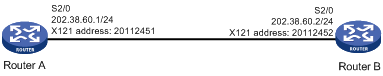
As shown in Figure 136, two routers are directly connected; IP packets can be transmitted between serial interfaces over the X.25 link layer protocol. Only one IP to X.121 mapping is available on Router A.
Figure 136: Network diagram
Configuration procedure
Configure Router A:
# Enter interface view.
<RouterA> system-view
[RouterA] interface serial 2/0
# Assign an IP address for the interface.
[RouterA-Serial2/0] ip address 202.38.60.1 255.255.255.0
# Configure the link layer protocol of the interface as X.25, and configure the interface to operate in DTE mode.
[RouterA-Serial2/0] link-protocol x25 dte
# Assign an X.121 address to the interface.
[RouterA-Serial2/0] x25 x121-address 20112451
# Configure the address mapping to the peer.
[RouterA-Serial2/0] x25 map ip 202.38.60.2 x121-address 20112452
# Configure the maximum packet size allowed and the window size.
[RouterA-Serial2/0] x25 packet-size 1024 1024
[RouterA-Serial2/0] x25 window-size 5 5
[RouterA-Serial2/0] shutdown
[RouterA-Serial2/0] undo shutdown
Configure Router B:
# Enter interface view.
<RouterB> system-view
[RouterB] interface serial 2/0
# Assign an IP address to the interface.
[RouterB-Serial2/0] ip address 202.38.60.2 255.255.255.0
# Configure the link layer protocol of the interface as X.25, and specify it to operate in DCE mode.
[RouterB-Serial2/0] link-protocol x25 dce
#Assign an X.121 address for the interface.
[RouterB-Serial2/0] x25 x121-address 20112452
# Configure address mapping to the peer.
[RouterB-Serial2/0] x25 map ip 202.38.60.1 x121-address 20112451
# Configure the maximum packet size allowed and the window size.
[RouterB-Serial2/0] x25 packet-size 1024 1024
[RouterB-Serial2/0] x25 window-size 5 5
[RouterB-Serial2/0] shutdown
[RouterB-Serial2/0] undo shutdown
Because the IP to X.121 mapping is available, IP addresses of both ends can be on different network segments and no static route is needed.
Verifying the configuration
The virtual circuit configured in this example is an SVC. The routers establish it only when they need to communicate.
# Ping Router B from Router A.
[RouterA-Serial2/0] ping 202.38.60.2
  PING 202.38.60.2: 56  data bytes, press CTRL_C to break
    Reply from 202.38.60.2: bytes=56 Sequence=1 ttl=255 time=33 ms
    Reply from 202.38.60.2: bytes=56 Sequence=2 ttl=255 time=27 ms
    Reply from 202.38.60.2: bytes=56 Sequence=3 ttl=255 time=26 ms
    Reply from 202.38.60.2: bytes=56 Sequence=4 ttl=255 time=26 ms
    Reply from 202.38.60.2: bytes=56 Sequence=5 ttl=255 time=26 ms

  --- 202.38.60.2 ping statistics ---
    5 packet(s) transmitted
    5 packet(s) received
    0.00% packet loss
    round-trip min/avg/max = 26/27/33 ms
The output shows that the SVC has been established between the two routers.
# Display the X.25 address mapping table on Router A.
[RouterA-Serial2/0] display x25 map
  Interface: Serial2/0(protocol status is UP)
    ip 202.38.60.2  X.121 address:20112452
      Map-type: SVC_MAP  VC-number: 1
      Facility:
# Display X.25 virtual circuit information on Router A.
[RouterA-Serial2/0] display x25 vc
Interface: Serial2/0
  SVC 1024
    State: P4(transmit)
    Map: ip 202.38.60.2 to 20112452
    Window size: input 5  output 5
    Packet Size: input 1024  output 1024
    Local PS: 5  Local PR: 5  Remote PS: 4  Remote PR: 5
    Local Busy: FALSE  Reset times: 0
    Input/Output:
      DATA 5/5  INTERRUPT 0/0
      RR 0/0  RNR 0/0  REJ 0/0
      Bytes 420/420
    Send Queue(Current/Max): 0/200