Configuring the basic parameters of an X.25 interface
Introduction to basic X.25 interface parameters
X.121 address
If the device is used for X.25 switching, this task can be skipped. If it is connected to an X.25 public packet network, set an X.121 address for the connected X.25 interface according to the requirements of the ISP. As defined in ITU-T recommendation X.121, an X.121 address is a string of 1 to 15 numbers.
X.25 operating mode
Layer 3 of X.25 supported by your device can operate in either DTE mode or DCE mode. The format of the datagram is alternative, either IETF or nonstandard.
An X.25 public packet switching network requires the device to access the network as a DTE and datagrams to be encapsulated with the IETF format generally. The operating mode of X.25 should be DTE and the encapsulation format should be IETF. When two routers are connected back to back through serial interfaces, make sure that they are using the same encapsulation format and are operating as the DTE and DCE, respectively.
X.25 virtual circuit range
The X.25 protocol can create multiple logical virtual connections over a physical link between DTE and DCE. These virtual connections are called virtual circuits or logical channels. Up to 4095 virtual circuits can be established by X.25, and the virtual circuit number is in the range of 1 to 4095. The number used to differentiate each virtual circuit (or logical channel) is called LCI or VCN.
Strictly speaking, virtual circuits and logical channels are different. However, at the user end, they are not distinguished strictly.
An important part of X.25 operation is how to manage the total 4095 virtual circuits.
All the virtual circuit numbers are divided into the following ranges (listed here in ascending order):
A—Permanent virtual circuits (PVCs) range.
B—Incoming-only channel range.
C—Two-way channel range.
D—Outgoing-only channel range.
The numbers of the virtual circuits established by an X.25 call must be set in the ranges of B, C, and D. The permanent virtual circuits must be set in the A range.
According to ITU-T Recommendation X.25, the idle channel allocation rules in initiating calls are as follows:
Only the DCE can initiate a call using a channel in the incoming-only channel range.
Only the DTE can initiate a call using a channel in the outgoing-only channel range.
Both the DCE and the DTE can initiate a call using a channel in the two-way channel range.
DCE always uses the lowest available logical channel.
DTE always uses the highest available logical channel.
You can avoid the case that one side of the communication occupies all the channels, and minimize the possibility of call collision.
As shown in Figure 124, in the X.25 protocol, six parameters are employed to define the four ranges.
Figure 124: X.25 channel delimitation
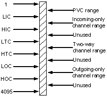
Table 4: X.25 channel range delimitation parameters
Parameter | Description |
|---|---|
LIC | Lowest Incoming-only Channel. |
HIC | Highest Incoming-only Channel. |
LTC | Lowest Two-way Channel. |
HTC | Highest Two-way Channel. |
LOC | Lowest Outgoing-only Channel. |
HOC | Highest Outgoing-only Channel. |
Each range (except PVC range) is defined by two parameters operating as the upper limit and lower limit. The parameters are in the range of 1 to 4095 (including 1 and 4095), but they are regarded correct only if they meet the following conditions:
In strict ascending order, 1 ≤ lic ≤ hic< ltc ≤ htc < loc ≤ hoc ≤ 4095.
If the upper limit (or lower limit) of a range is 0, then the lower limit (or upper limit) must also be 0, (which indicates this range is disabled from use).
Finally, follow these guidelines:
At the two sides (DTE and DCE) of a physical connection, these six parameters of X.25 must be equal in a symmetric way, because different settings at the two sides are very likely to result in an improper procedure and result in transmission failures.
Take the default of each parameter into consideration.
The new configuration cannot take effect immediately on a connection in use unless you reset the interface by using the commands shutdown and undo shutdown.
X.25 packet numbering modulo
The implementation of X.25 supports both modulo 8 and modulo 128 in packet numbering, with modulo 8 being the default.
The X.25 protocol requires DTE and DCE have the same packet sequence numbering mode. The new configuration is not effective unless you reset the interface by using the shutdown command and the undo shutdown command.
Besides, the packet sequence numbering mode of X.25 layer 3 is different from the frame sequence numbering mode of LAPB (X.25 layer 2). When modulo 128 numbering mode is employed in the DTE/DCE interface with high throughput rate, for LAPB, only the efficiency of local DTE/DCE interface is affected, and point-to-point efficiency increases. For X.25 layer 3, the efficiency of end-to-end is affected, and the efficiency between the two DTEs increases.
Traffic control parameters
X.25 protocol is a reliable transport protocol with powerful traffic control capability due to the "window size" and "maximum packet size." However, it cannot perform traffic control effectively and correctly unless correctly configured. Any inappropriate configuration will cause CLEAR and RESET events of X.25.
Because most public X.25 packet networks use the default window size and maximum packet size specified in the ITU-T X.25 Recommendation, the device also adopts the same default values. You do not need to set the two parameters unless requested by the access service providers.
After the default window size and the default maximum packet size are set, the SVC, which can be established only through calling, will use these default values if related parameters are not negotiated in the call process (parameter negotiation will be described in later sections). The PVC, which can be established directly without calling, will also use these default values if no window size or packet size option is appended when it is specified. (See later sections for PVC configuration).
An X.25 sender will fragment the oversized data packets at the upper layer based on the maximum packet size, and mark the final fragment packet (M bit not set). After the packets reach the receiver, X.25 will reassemble the fragment packets, and determine whether a piece of complete upper layer packet is received based on the M bit flag. Too small value of the maximum packet size will consume too much router resources on message fragmenting and reassembling, and lower efficiency.
The maximum packet size < MTU*8 < N1 of LAPB
Reset an interface by using the shutdown and undo shutdown commands to make a new configuration take effect
Configuration procedure
To configure an X.25 interface:
Step | Command | Remarks |
|---|---|---|
1. Enter system view. | system-view | N/A |
2. Enter interface view. | interface interface-type interface-number | N/A |
3. Enable X.25 encapsulation on the interface. | link-protocol x25 [ dce |dte ] [ ietf | nonstandard ] | The default setting is PPP. With X.25 encapsulation enabled, the default operation mode is DTE IETF. |
4. Set an X.121 address for the interface. | x25 x121-address x.121-address | Optional. If the device is used for the purpose of X.25 switching, this task can be skipped. If it is connected to X.25 public packet network, set an X.121 address for the connected X.25 interface. |
5. Set the X.25 virtual circuit range. | x25 vc-range { bi-channel ltc htc [ out-channel loc hoc ] | in-channel lic hic [ bi-channel ltc htc ] [ out-channel loc hoc ] | out-channel loc hoc } | Optional. By default, lower and upper limits of a two-way channel are 1 and 1024, respectively, those of incoming-only channel are both 0, and those of outgoing-only channel are both 0. To make the configuration take effect, re-enable the interface by using the shutdown and then undo shutdown commands. |
6. Set the modulo. | x25 modulo { 8 | 128 } | Optional. The default setting is 8. To make the configuration take effect, re-enable the interface by using the shutdown and then undo shutdown commands. |
7. Set the sizes of virtual circuit input window and output window. | x25 window-size input-window-size output-window-size | Optional. By default, input-window-size is 2 and output-window-size is 2. To make the configuration take effect, re-enable the interface by using the shutdown and then undo shutdown commands. |
8. Set the maximum sizes for input and output packets on the interface. | x25 packet-size input-packet output-packet | Optional. By default, input-packet is 128 bytes and output-packet is 128 bytes. To make the configuration take effect, re-enable the interface by using the shutdown and then undo shutdown commands. |