ATM PVC transmit priority configuration example
Network requirements
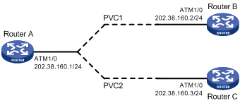
As shown in Figure 72, create PVC 1 and PVC 2 on the same ATM 155 Mbps interface, each assigned 100 Mbps of bandwidth and associated with the UBR service. Set the transmission priority of PVC 1 to 1 and that of PVC 2 to 3.
Configure Router A to distribute equal amount of traffic to Router B and Router C on two PVCs and observe the statistics about received/sent/dropped packets.
Figure 72: Network diagram
Configuration procedure
Configure Router A
# Configure the ATM interface.
<RouterA> system-view
[RouterA] interface atm 1/0
[RouterA-Atm1/0] ip address 202.38.160.1 255.255.255.0
# Create two PVCs and assign them different transmission priority values.
[RouterA-Atm1/0] pvc 1 0/33
[RouterA-atm-pvc-Atm1/0-0/33-1] map ip 202.38.160.2
[RouterA-atm-pvc-Atm1/0-0/33-1] service ubr 100000
[RouterA-atm-pvc-Atm1/0-0/33-1] transmit-priority 1
[RouterA-atm-pvc-Atm1/0-0/33-1] quit
[RouterA-Atm1/0] pvc 2 0/32
[RouterA-atm-pvc-Atm1/0-0/32-2] map ip 202.38.160.3
[RouterA-atm-pvc-Atm1/0-0/32-2] service ubr 100000
[RouterA-atm-pvc-Atm1/0-0/33-1] transmit-priority 3
After two equal traffic flows exceeding the ATM bandwidth are sent to Router B and Router C, you can use the display atm pvc-info interface atm 1/0/0 pvc command on Router B and Router C to view statistics for each PVC (you can make several tests and observe the average statistics). You can see that the PVC with higher priority receives more packets than that with lower priority. The PVC with the higher priority takes preference in getting bandwidth and other PVCs (if there are many and with different priority values), regardless of their priority values, are treated equally in terms of bandwidth allocation.