MFR direct connection configuration example
Network requirements
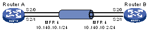
As shown in Figure 34, Router A and Router B are directly connected through Serial 2/0 and Serial 2/1. The frame relay protocol bundles the two serial ports to provide broader bandwidth.
Figure 34: Network diagram
Configuration procedure
Configure Router A:
# Create and configure MFR interface 4 (MFR4).
<RouterA> system-view
[RouterA] interface mfr 4
[RouterA-MFR4] ip address 10.140.10.1 255.255.255.0
[RouterA-MFR4] fr interface-type dte
[RouterA-MFR4] fr map ip 10.140.10.2 100
[RouterA-MFR4] quit
# Bundle Serial 2/0 and Serial 2/1 to MFR4.
[RouterA] interface serial 2/0
[RouterA-Serial2/0] link-protocol fr mfr 4
[RouterA-Serial2/0] quit
[RouterA] interface serial 2/1
[RouterA-Serial2/1] link-protocol fr mfr 4
Configure Router B:
# Create and configure MFR interface 4 (MFR4).
<RouterB> system-view
[RouterB] interface mfr 4
[RouterB-MFR4] ip address 10.140.10.2 255.255.255.0
[RouterB-MFR4] fr interface-type dce
[RouterB-MFR4] fr dlci 100
[RouterB-fr-dlci-MFR4-100] quit
[RouterB-MFR4] fr map ip 10.140.10.1 100
[RouterB-MFR4] quit
# Bundle Serial 2/0 and Serial 2/1 to MFR4.
[RouterB] interface serial 2/0
[RouterB-Serial2/0] link-protocol fr mfr 4
[RouterB-Serial2/0] quit
[RouterB] interface serial 2/1
[RouterB-Serial2/1] link-protocol fr mfr 4