Connecting LANs through an Annex G DLCI
Network requirements
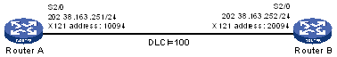
As shown in Figure 30, Router A and Router B are connected with serial interfaces. It is desirable to use frame relay PVCs to transmit X.25 packets. Router A operates as the DCE and Router B operates as the DTE.
Figure 30: Network diagram
Configuration procedure
Configure Router A:
# Create an X.25 template.
<RouterA> system-view
[RouterA] x25 template vofr
# Configure the local X.25 address.
[RouterA-x25-vofr] x25 x121-address 10094
# Configure the X.25 address mapping to the destination IP address.
[RouterA-x25-vofr] x25 map ip 202.38.163.252 x121-address 20094
 [RouterA-x25-vofr] quit
# Assign an IP address to the local interface.
[RouterA] interface serial 2/0
[RouterA–Serial2/0] ip address 202.38.163.251 255.255.255.0
# Enable frame relay on the interface and configure the interface to operate in DCE mode.
[RouterA–Serial2/0] link-protocol fr
[RouterA–Serial2/0] fr interface-type dce
# Create a PVC.
[RouterA–Serial2/0] fr dlci 100
# Configure the PVC to operate in Annex G DCE mode.
[RouterA-fr-dlci-Serial2/0-100] annexg dce
# Apply the X.25 template to the PVC.
[RouterA-fr-dlci-Serial2/0-100] x25-template vofr
[RouterA-fr-dlci-Serial2/0-100] quit
# Configure the FR address mapping to the destination IP address.
[RouterA–Serial2/0] fr map ip 202.38.163.252 100
Configure Router B:
# Create an X.25 template.
<RouterB> system-view
[RouterB] x25 template vofr
# Configure the local X.25 address.
[RouterB-x25-vofr] x25 x121-address 20094
# Configure the X.25 address mapping to the destination IP address.
[RouterB-x25-vofr] x25 map ip 202.38.163.251 x121-address 10094
[RouterB-x25-vofr] quit
# Assign an IP address to the local interface.
[RouterB] interface serial 2/0
[RouterB–Serial2/0] ip address 202.38.163.252 255.255.255.0
# Enable frame relay on the interface and configure the interface to operate in DTE mode.
[RouterB–Serial2/0] link-protocol fr
[RouterB–Serial2/0] fr interface-type dte
# Create a frame relay PVC.
[RouterB–Serial2/0] fr dlci 100
# Configure the PVC to operate in Annex G DTE mode.
[RouterB-fr-dlci-Serial2/0-100] annexg dte
# Apply the X.25 Template to the PVC.
[RouterB-fr-dlci-Serial2/0-100] x25-template vofr
[RouterB-fr-dlci-Serial2/0-100] quit
# Configure the FR address mapping to the destination IP address.
[RouterB–Serial2/0] fr map ip 202.38.163.251 100