MP configuration example
Network requirements
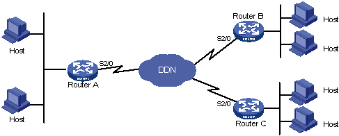
As shown in Figure 8:
On an E1 interface of Router A, four channels are created with the interface names Serial 2/0:1, Serial 2/0:2, Serial 2/0:3, and Serial 2/0:4.
On Router B, two channels are created with the interface names Serial 2/0:1 and Serial 2/0:2. It is the same case with Router C.
Do the following:
Bind two channels on Router A with the two channels on Router B and another two channels with the two channels on Router C.
Adopt binding authentication.
Figure 8: Network diagram
Configuration procedure
Configure Router A:
# Create user accounts for Router B and Router C and set the passwords.
<RouterA> system-view
[RouterA] local-user router-b
[RouterA-luser-router-b] password simple router-b
[RouterA-luser-router-b] service-type ppp
[RouterA-luser-router-b] quit
[RouterA] local-user router-c
[RouterA-luser-router-c] password simple router-c
[RouterA-luser-router-c] service-type ppp
[RouterA-luser-router-c] quit
# Create two VT interfaces for the two user accounts.
[RouterA] ppp mp user router-b bind virtual-template 1
[RouterA] ppp mp user router-c bind virtual-template 2
# Configure the VT interfaces.
[RouterA] interface virtual-template 1
[RouterA-Virtual-Template1] ip address 202.38.166.1 255.255.255.0
[RouterA-Virtual-Template1] quit
[RouterA] interface virtual-template 2
[RouterA-Virtual-Template2] ip address 202.38.168.1 255.255.255.0
[RouterA-Virtual-Template2] quit
# Add interfaces Serial 2/0:1, Serial 2/0:2, Serial 2/0:3, and Serial 2/0:4 to MP channels. Take Serial 2/0:1 as an example.
[RouterA] interface serial 2/0:1
[RouterA-Serial2/0:1] link-protocol ppp
[RouterA-Serial2/0:1] ppp mp
[RouterA-Serial2/0:1] ppp authentication-mode pap domain system
[RouterA-Serial2/0:1] ppp pap local-user router-a password simple router-a
[RouterA-Serial2/0:1] quit
# Configure local authentication for the PPP users in the default ISP domain system.
[RouterA] domain system
[RouterA-isp-system] authentication ppp local
Configure Router B:
# Create a user account for Router A.
<RouterB> system-view
[RouterB] local-user router-a
[RouterB-luser-router-a] password simple router-a
[RouterB-luser-router-a] service-type ppp
[RouterB-luser-router-a] quit
# Create a VT interface for the user and specify to use the NCP information of this interface for PPP negotiation.
[RouterB] ppp mp user router-a bind virtual-template 1
# Configure the VT interface.
[RouterB] interface virtual-template 1
[RouterB-Virtual-Template1] ip address 202.38.166.2 255.255.255.0
[RouterB-Virtual-Template1] quit
# Add interfaces Serial 2/0:1 and Serial 2/0/:2 to the MP channel. Take Serial 2/0:1 as an example.
[RouterB] interface serial 2/0:1
[RouterB-Serial2/0:1] ppp mp
[RouterB-Serial2/0:1] ppp authentication-mode pap domain system
[RouterB-Serial2/0:1] ppp pap local-user router-b password simple router-b
[RouterB-Serial2/0:1] quit
# Configure local authentication for the PPP users in the default ISP domain system.
[RouterB] domain system
[RouterB-isp-system] authentication ppp local
Configure Router C:
# Create a user account for Router A.
<RouterC> system-view
[RouterC] local-user router-a
[RouterC-luser-router-a] password simple router-a
[RouterC-luser-router-a] service-type ppp
[RouterC-luser-router-a] quit
# Create a VT interface for the user and specify to use the NCP information of the interface for PPP negotiation.
[RouterC] ppp mp user router-a bind virtual-template 1
# Configure the VT interface.
[RouterC] interface virtual-template 1
[RouterC-Virtual-Template1] ip address 202.38.168.2 255.255.255.0
[RouterC-Virtual-Template1] quit
# Add interfaces Serial 2/0:1 and Serial 2/0:2 to the MP channel. Take Serial 2/0:1 as an example.
[RouterC] interface serial 2/0:1
[RouterC-Serial2/0:1] ppp mp
[RouterC-Serial2/0:1] ppp authentication-mode pap domain system
[RouterC-Serial2/0:1] ppp pap local-user router-c password simple router-c
[RouterC-Serial2/0:1] quit
# Configure local authentication for the PPP users in the default ISP domain system. .
[RouterC] domain system
[RouterC-isp-system] authentication ppp local