PQ configuration example
Network requirements
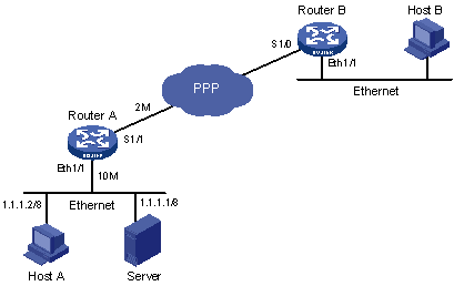
As shown in Figure 20, both Server and Host A send data to Host B through Router A. Suppose Server sends critical packets and Host A sends non-critical packets. Congestion might occur on Serial 1/1 and result in packet loss because the rate of the incoming interface Ethernet 1/1 is greater than that of the outgoing interface Serial 1/1 on Router A.
Configure PQ, so that the critical packets from Server are transmitted preferentially when congestion occurs in the network.
Figure 20: Network diagram
Configuration procedure
Configure Router A:
# Configure ACLs to match the packets from Server and Host A, respectively.
[RouterA] acl number 2001
[RouterA-acl-basic-2001] rule permit source 1.1.1.1 0.0.0.0
[RouterA] acl number 2002
[RouterA-acl-basic-2002] rule permit source 1.1.1.2 0.0.0.0
# Configure a PQ list that assigns the packets from Server to the top queue and those from Host A to the bottom queue when congestion occurs. Set the maximum queue size of the top queue to 50 and that of the bottom queue to 100 in the PQ list.
[RouterA] qos pql 1 protocol ip acl 2001 queue top
[RouterA] qos pql 1 protocol ip acl 2002 queue bottom
[RouterA] qos pql 1 queue top queue-length 50
[RouterA] qos pql 1 queue bottom queue-length 100
# Apply PQ list 1 to Serial 1/1.
[RouterA] interface serial 1/1
[RouterA-Serial1/1] qos pq pql 1