Setup Overview
for the HP ProLiant MicroServer Gen8
Before you begin
- For safety, environmental, and regulatory information, see Safety and Compliance Information for Server, Storage, Power, Networking, and Rack Products on the HP website.
- Select an installation site that meets the detailed installation site requirements described in the server user guide.
- Unpack the server shipping carton, and locate the materials and documentation necessary for installing the server.
- Verify operating system support—For information about operating systems supported by ProLiant servers, see the operating system support matrices.
For more pre-installation information, see the HP ProLiant MicroServer Gen8 User Guide.
Component identification
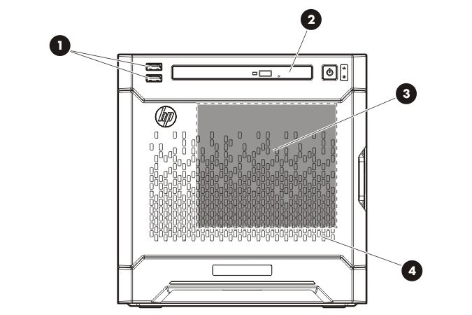
Front panel components
Item |
Description |
|---|---|
1 |
USB 2.0 connectors |
2 |
Optical drive (optional) |
3 |
Drive bays (inside) |
4 |
Front bezel |
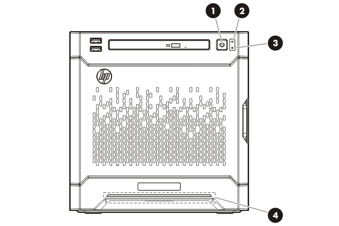
Front panel LEDs and buttons
Item |
Description |
Status |
|---|---|---|
1 |
Power On/Standby button and system power LED |
Solid green = System on Flashing green (1 Hz/cycle per sec) = Performing power on sequence Solid amber = System in standby Off = No power present* |
2 |
NIC status LED |
Solid green = Link to network Flashing green (1 Hz/cycle per sec) = Network active Off = No network activity |
3 |
Drive status LED |
Solid green = System on Flashing green = Drive activity Off = System in standby or no power present |
4 |
Health LED |
Solid blue = Normal Flashing amber = System degraded Flashing red (1 Hz/cycle per sec) = System critical Fast-flashing red (4 Hz/cycles per sec) = Power fault** |
* Facility power is not present, power cord is not attached, no power supplies are installed, power supply failure has occurred, or the power button cable is disconnected.
** To identify components in a degraded or critical state, see the iLO/BIOS logs and the server troubleshooting guide.
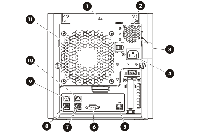
Rear panel components
Item |
Description |
|---|---|
1 |
Kensington security slot |
2 |
Power supply |
3 |
Serial number/iLO information tag* |
4 |
Power cord connector |
5 |
Dedicated iLO connector |
6 |
Video connector |
7 |
USB 3.0 connectors |
8 |
USB 2.0 connectors |
9 |
NIC connector 2 |
10 |
NIC connector 1/shared iLO connector |
11 |
System fan |
* The serial number/iLO information tag shows the server serial number and the default iLO account information. The same information is printed on separate labels located on the rear panel.
Rear panel LEDs
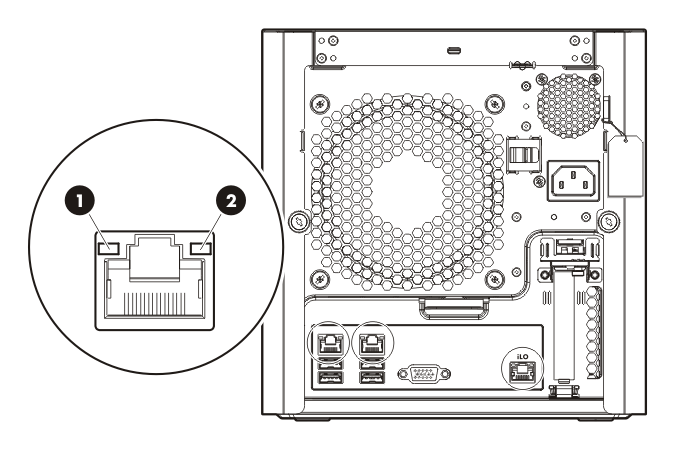
Item |
Description |
Status |
|---|---|---|
1 |
NIC link LED |
Solid green = Link exists Off = No link exists |
2 |
NIC status LED |
Solid green = Link to network Flashing green (1 Hz/cycle per sec) = Network active Off = No network activity |
Install hardware options
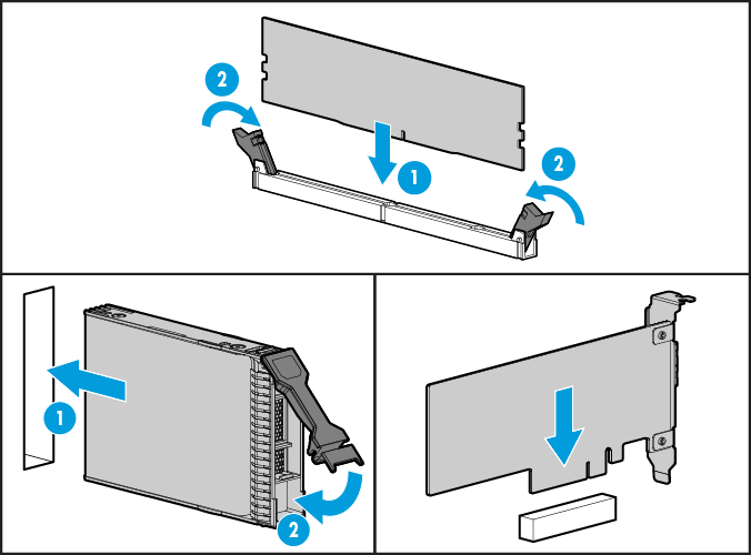
For options installation information, see the documentation that ships with the option. For server‑specific information, see the HP ProLiant MicroServer Gen8 User Guide.
Connect peripheral devices
The I/O connectors are color coded and are marked with icons.
The server has seven USB connectors:
- Four external USB 2.0
 connectors, two each on the front and rear panels
 - Two external rear USB 3.0
 connectors
 - One internal USB 2.0 connector on the system board
The system ROM has inherent USB 2.0 ![]() support. These connectors are functional even before the OS loads. During the initial server setup or when configuring BIOS settings, connect USB devices to the USB 2.0
support. These connectors are functional even before the OS loads. During the initial server setup or when configuring BIOS settings, connect USB devices to the USB 2.0 ![]() connectors.
connectors.
The USB 3.0 ![]() connectors are OS-dependent. These connectors are functional only after the OS loads. Furthermore, the following two OSs require the installation of the USB 3.0 device driver:
connectors are OS-dependent. These connectors are functional only after the OS loads. Furthermore, the following two OSs require the installation of the USB 3.0 device driver:
- Microsoft Windows Server 2008 SP2 (x86 and x86-64 editions)
- Microsoft Windows Server 2008 R2 SP1
The USB 3.0 driver is included in the SPP download when performing an Intelligent Provisioning-assisted system setup. For more information about Intelligent Provisioning drivers, firmware, and SPP, see the HP website.
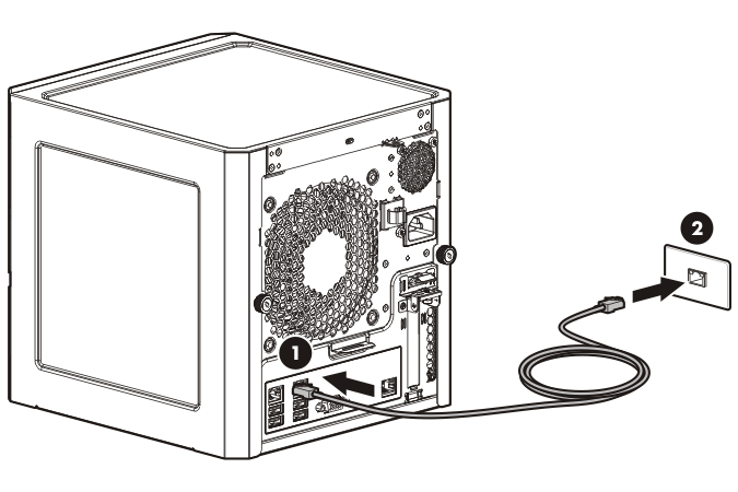
Connect the Ethernet cable
The server supports the following Ethernet connectors located on the rear panel:
- NIC 1/shared iLO connector

- NIC 2 connector

- Dedicated iLO connector

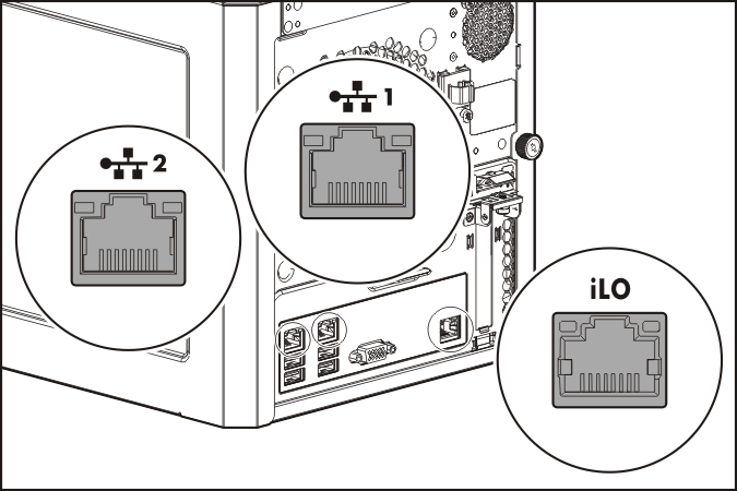
To connect an Ethernet cable:
- Connect one end of the Ethernet cable to the NIC 1 connector.
- Connect the other end of the Ethernet cable to a network jack.
Power on and select boot options
|
WARNING: To reduce the risk of electric shock or damage to the equipment:
|
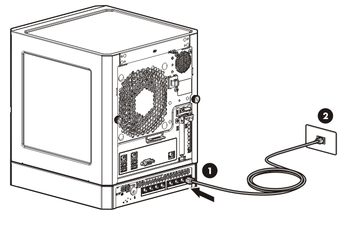
- Connect the power cord to the server.
- Open the power cord retaining clip, and then thread the power cord through the strain relief clip.
- To secure the power cord, snap the clip into place.
- Connect the power cord to the AC power source.
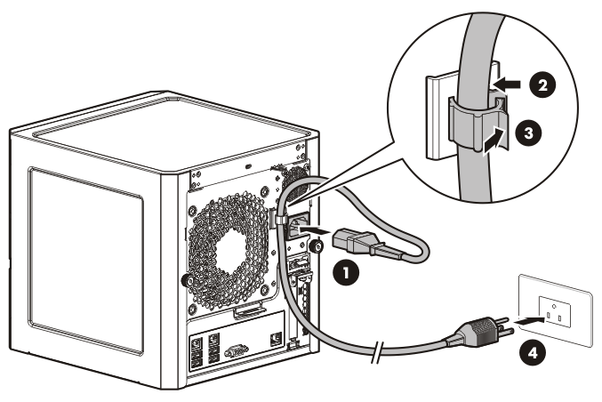
The server automatically turns on after the power cord is connected.
- Check the server Power LED status
 . The LED flashes green to indicate that power connection is established.
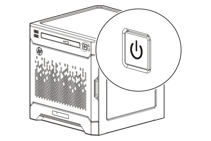
- During the initial server boot (POST), do one of the following:
- For advanced users, to modify the server configuration ROM default settings, press F9 when prompted to enter the RBSU. By default, the RBSU runs in the English language.
- To retain the HP recommended default server configuration and install the operating system, press F10 to initiate Intelligent Provisioning. Proceed to the next section.
For more information on automatic server configuration, see the HP ROM-Based Setup Utility User Guide in the HP RBSU Information Library.
Perform the initial system setup
HP recommends using Intelligent Provisioning to install the server operating system. All firmware, drivers, and tools required by the system are installed during the same process.
Intelligent Provisioning provides installation help for the following operating systems: Microsoft Windows, Red Hat and SUSE Linux, and VMware.
|
IMPORTANT: When installing a Windows operating system, Intelligent Provisioning can assist with installing only the 64-bit version of the operating system. |
|
IMPORTANT: Installing VMware ESXi or ESX requires a custom HP image, which includes the drivers for VMware devices not included in the VMware base image. The image is available on the HP website. |
Activate Intelligent Provisioning
Follow the prompts on the Set Preferences screen to activate Intelligent Provisioning.
If you intend to register for HP Insight Remote Support, you should have your HP Passport user name and password ready. For more information, see the HP Insight Remote Support and Insight Online Setup Guide for ProLiant Gen8 Servers and HP BladeSystem c-Class Enclosures on the HP website.
Configure the drive
If you intend to use an HP Smart Array controller card option, record the model name for this procedure.
For more information about the storage controller and its features, select the relevant controller user documentation on the HP website.
To configure arrays, see the HP Smart Storage Administrator User Guide on the HP website.
To create a drive array:
- On the Intelligent Provisioning main screen, click Perform Maintenance.
- On the Maintenance screen, click HP Smart Storage Administrator (HP SSA).
The system launches the HP SSA GUI.
- On the left-hand side of the screen, select the preferred HP Smart Array Controller device, and then click Configure under the available options.
The Configure panel is displayed.
- Click Create Array.
- Select the array settings for the selected device.
- Use the Next and Back buttons to navigate multiple screens of options.
- Click Save or OK.
- Click Exit HP SSA.
- Click
 PREVIOUS.
Install the operating system
- If you are installing the OS from a disc or an external USB drive, do one of the following:
- Load the OS image disc to the server optical drive. If an optical drive is not installed, connect a USB optical drive to the server USB 2.0 connector.
- Connect the USB storage drive containing the OS image to the server USB 2.0 connector.
- Load the OS image disc to the server optical drive. If an optical drive is not installed, connect a USB optical drive to the server USB 2.0
- On the Intelligent Provisioning main screen, select Configure and Install.
- The system detects the default hardware settings. Retain these settings or customize them according to your requirements.
- Follow the onscreen prompts to install the OS.
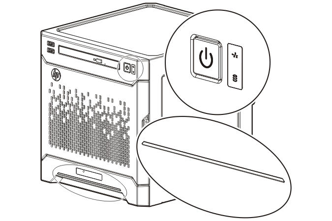
Complete the system setup
Check the status of the server LEDs to ensure that the server is operating normally:
- System power LED —Solid green
- NIC status LED
 —Solid green
 - Drive status LED
 —Solid green
 - Health LED bar—Solid blue
For server management tasks after the initial server setup, use either the dedicated iLO connector ![]() (enabled by default) or the NIC 1/shared iLO connector
(enabled by default) or the NIC 1/shared iLO connector ![]() (It is disabled by default. Enable the shared iLO function in iLO RBSU).
(It is disabled by default. Enable the shared iLO function in iLO RBSU).
For more information on iLO management tasks, see the HP website.
Use the MicroServer with the HP PS1810-8G switch (optional)
If you intend to use the server with the companion HP PS1810-8G Switch, follow the procedures in this section.
For more information on switch-related settings and operational procedures, see the HP website.
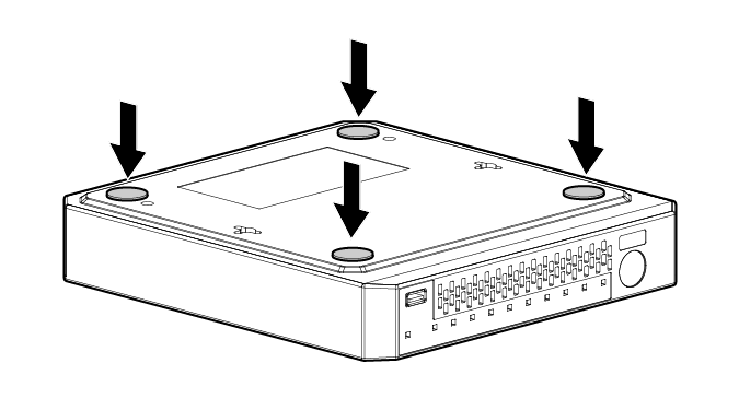
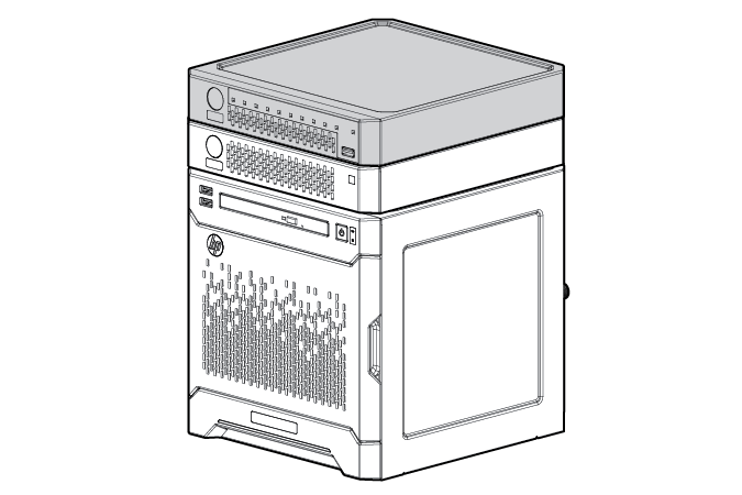
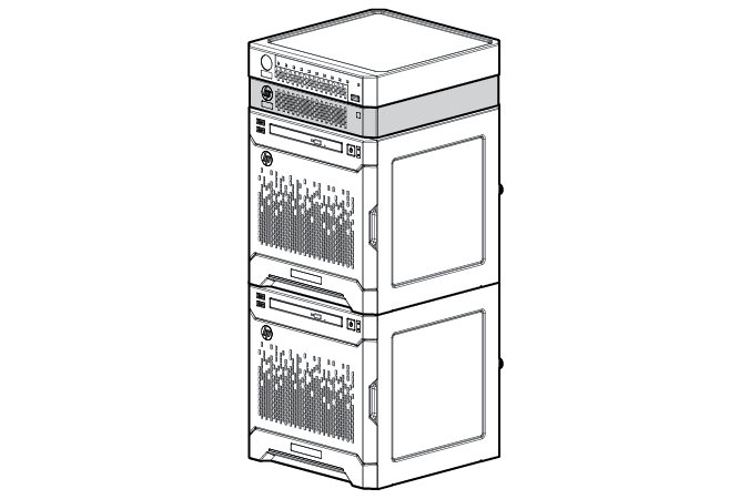
Mount the switch with the server
- Attach the self-adhesive rubber pads to the bottom surface of the switch.
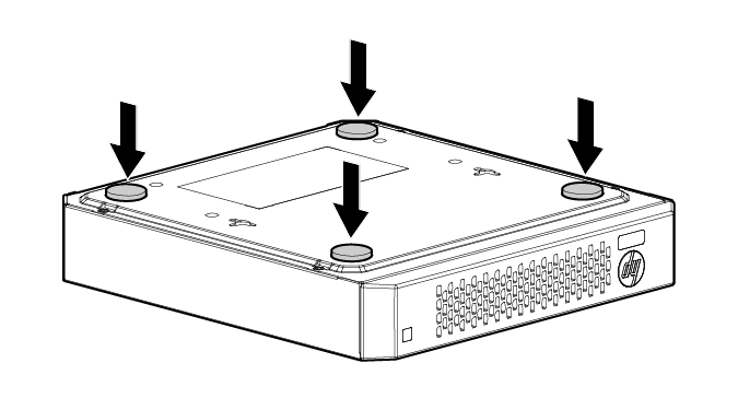

CAUTION: The switch has a limitation on how much weight can be placed on top of it. To reduce the risk of personal injury or damage to the equipment because of an unstable server-switch stacking, stack no more than two servers on top of the switch.
- Stack the switch on either the top or the bottom of the server.
If you are stacking the switch on the top of the server, you can stack up to three MicroServers.
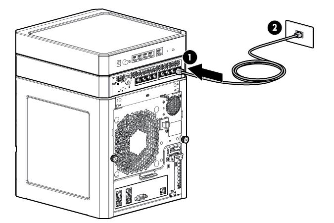
Complete the switch Self-Test
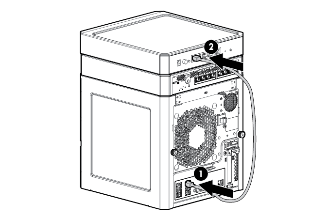
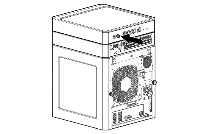
- Connect an Ethernet cable to the switch, and then connect the cable to a network jack.
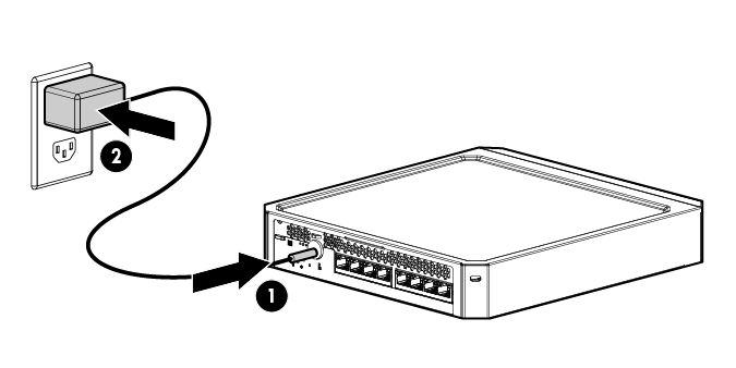
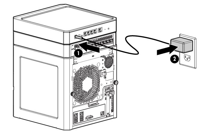
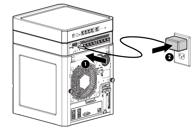
- If you are using a wall-mount power adapter, do the following:
- Connect the power adapter to the switch.
- Connect the power adapter to the AC power source.
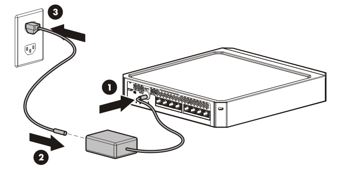
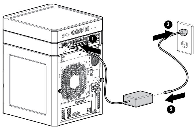
- If you are using an in-line power adapter, do the following:
- Connect the power adapter to the switch.
- Connect the power cord to the adapter.
- Connect the power cord to the AC power source.
- Check the status of the switch Power LED. This LED is solid green to indicate that the power connection is established.
- Check the status of the following switch LEDs:
- Link/Act LED on the switch network port that is being used—Initially, solid green to indicate successful connection, and then flashing green to indicate active communication with the network.
- Fault LED—Remains off to indicate successful Self-Test completion.
For more information on the location of the switch LEDs and their behavior during the Self-Test process, see the switch documentation.
Connect the server to the switch
You can connect the server to the switch through the following methods:
- A simple Ethernet connection with no iLO functionality
- An Ethernet connection with iLO functionality using the dedicated iLO connector
- An Ethernet connection with iLO functionality using the shared iLO connector
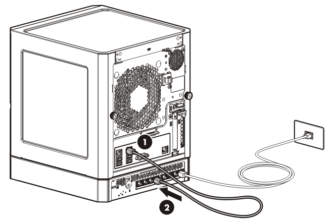
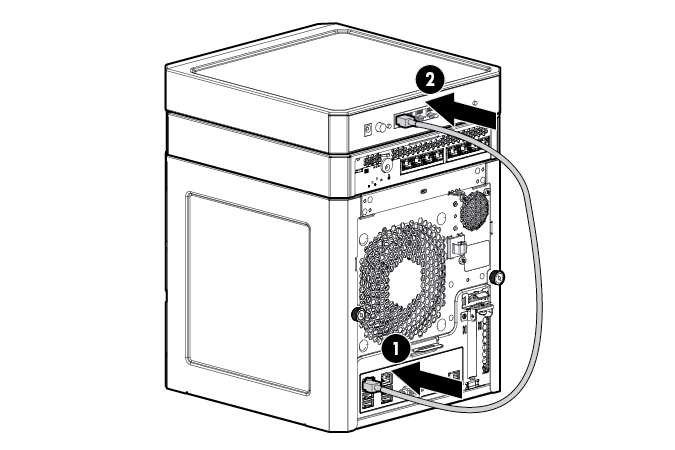
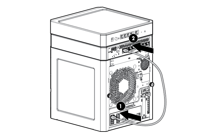
To establish a simple Ethernet connection:
- Connect an Ethernet cable to the server NIC connector 1 or 2.
- Connect the cable to any switch LAN port.
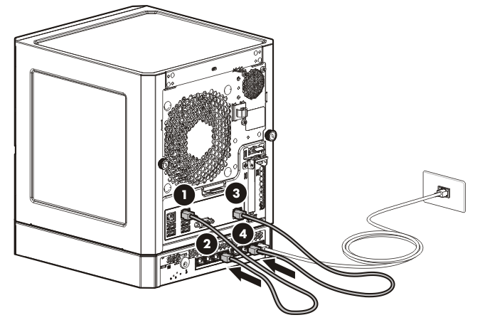
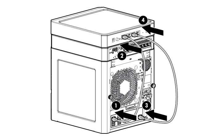
To establish an Ethernet connection with iLO functionality by using the dedicated iLO connector:
- Connect an Ethernet cable to the server NIC 1 or NIC 2 connector, and then connect the cable to a switch LAN port.
- Connect the cable to any switch LAN port.
- Connect an Ethernet cable to the server dedicated iLO connector, and then connect the cable to any switch LAN port.
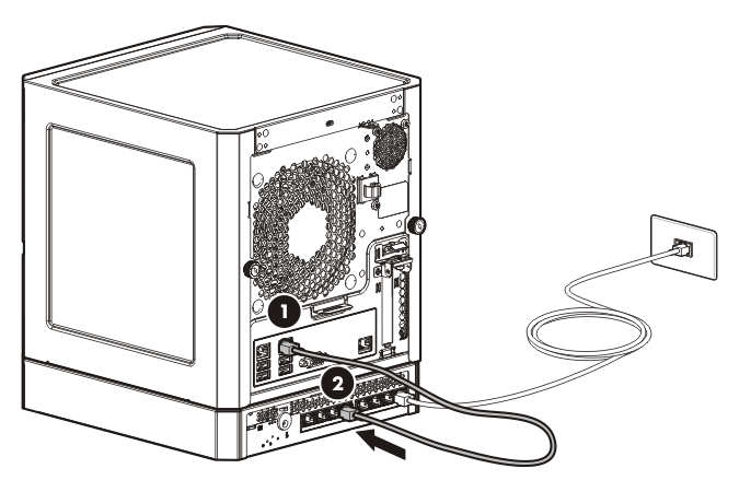
To establish an Ethernet connection with iLO functionality by using the shared iLO connector:
- Enable the shared iLO functionality of the server.
- Connect an Ethernet cable to the server NIC 1/shared iLO connector, and then connect the cable to any switch LAN port.
Complete the switch setup
After the Ethernet cable connection is made, check the network LED status on both the server and the switch to confirm successful connection:
- In the server front panel, the NIC status LED —Solid green
- In the switch, the Link/Act LED on the network connector used—Initially, solid green to indicate successful connection, and then flashing green to indicate active communication with the network.
Use the MicroServer with the HP PS110 802. 11n Wireless VPN Router and the HP PS 1810 Switch (optional)
The HP PS110 802.11n Wireless VPN Router and the HP PS1810-8G Switch are companion networking options for the HP ProLiant MicroServer Gen8.
Follow these instructions to set up the router and switch with the server:
- Set up the router.
- Set up the switch.
For more information on the setup and operational procedures for these networking options, see the following websites:
HP PS110 802. 11n Wireless VPN router setup procedures
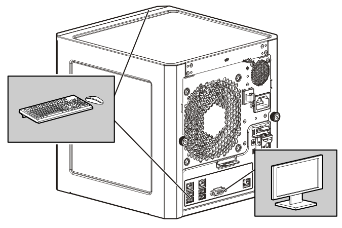
Configure the server for use with the router
By default, the PS110 VPN router will function as a DHCP server.
- Connect a monitor, keyboard, and mouse to the server.
- Verify that the Ethernet network interface of the server is set to obtain an IP address automatically from a DHCP server. Do the following:
- Click Control Panel ® Network and Sharing Center.
- In the View your active networks section, click Local Area Connection.
- In the Local Area Connection Status window, click Properties.
- Select the Internet Protocol Version 4 option, and then click Properties.
- To enable the DHCP server functionality, select the Obtain IP address automatically and Obtain DNS server address automatically options.
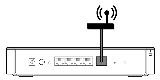
Mount the router on the server
- Attach the self-adhesive rubber pads to the bottom surface of the router.
- Mount the router on the very top of a stack of servers and associated devices.
To achieve maximum wireless coverage, the PS110 must be placed on the very top of the stack of all MicroServer devices. For example, if you are using an HP PS1810-8G Switch on top of the MicroServer, the PS110 router must be placed on top of the switch.
Connect the server to the router
You can connect the server to the router through the following methods:
- A simple Ethernet connection with no iLO functionality
- An Ethernet connection with iLO functionality, using the dedicated iLO connector
- An Ethernet connection with iLO functionality, using the shared iLO connector
To connect the server to the router:
- Connect a standard Ethernet cable from the modem to the router WAN port.
- If you prefer to have an Ethernet connection with no iLO functionality, do the following:
- Connect an Ethernet cable to the server NIC connector 1 or 2.
- Connect the cable to the router LAN port.
- If you prefer to have an Ethernet connection with dedicated iLO functionality, do the following:
- Connect an Ethernet cable to the server NIC 1 or NIC 2 connector, and then connect the cable to a router LAN port.
- Connect another Ethernet cable to the server dedicated iLO connector, and then connect the cable to a router LAN port.
- If you prefer to have an Ethernet connection with shared iLO functionality, do the following:
- Enable the shared iLO functionality of the server.
- Connect an Ethernet cable to the server NIC 1/shared iLO connector, and then connect the cable to the router LAN port.
Power on and configure the router
- Connect the power adapter to the router.
- Connect the power cord to the AC power source.
- Press the router power button.
The LEDs on the router LAN ports flashes on and off for approximately one minute. When the router Alert LED turns off, proceed to the next step.
For more information on the location of the router LEDs and their behavior during the initial router configuration process, see the router documentation.
- Log in to the router management interface page and run the setup wizard.
For detailed instructions for this step, see the Quickstart document that shipped with the router.
HP PS1810-8G Switch setup procedures
For deployments requiring more than four network ports on the router, HP recommends adding the HP PS1810-8G Switch.
Mount the switch with the server
- Attach the self-adhesive rubber pads to the bottom surface of the switch.
CAUTION: The switch has a limitation on how much weight can be placed on top of it. To reduce the risk of personal injury or damage to the equipment because of an unstable server-switch stacking, stack no more than two servers on top of the switch.
- Stack the switch with the server:
- Bottom stacking—Stack the server on top of the switch.
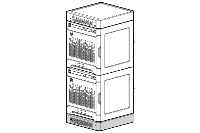
- Top stacking—Stack the switch on the top of the server. You can stack up to three MicroServers.
- Bottom stacking—Stack the server on top of the switch.
Complete the switch Self-Test
- Connect an Ethernet cable to the switch, and then connect the cable to a network jack.
- If you are using a wall-mount power adapter, do the following:
- Connect the power adapter to the switch.
- Connect the power adapter to the AC power source.
- If you are using an in-line power adapter, do the following:
- Connect the power adapter to the switch.
- Connect the power cord to the adapter.
- Connect the power cord to the AC power source.
- Check the status of the switch Power LED. This LED is solid green to indicate that the power connection is established.
- Check the status of the following switch LEDs:
- Link/Act LED on the switch network port that is being used—Initially, solid green to indicate successful connection, and then flashing green to indicate active communication with the network.
- Fault LED—Remains off to indicate successful Self-Test completion.
For more information on the location of the switch LEDs and their behavior during the Self-Test process, see the switch documentation.
Connect the switch to the router
- The HP recommended setup configuration is for the server to be connected to the switch LAN port only. As such, disconnect the Ethernet cable connecting the router LAN port to the server NIC connector.
- Connect an Ethernet cable to a switch LAN port, and then connect the cable to a router LAN port.
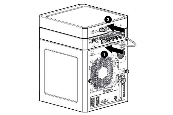
- Connect an Ethernet cable to a switch LAN port , and then connect the cable to the NIC 1 or NIC 2 connector on the server.
Enable the MicroServer shared iLO functionality
The shared iLO functionality on the server is disabled by default. To use this functionality, do the following:
- Access the iLO RBSU by rebooting the server, and then pressing F8 during POST.
- Under the Network menu, select the NIC TCP/IP option.
- Set the Network Interface Adapter field to Shared Network Port — LOM.
- To save the change, press F10.
- To close the iLO RBSU, under the File menu, select the Exit option.
Register the server
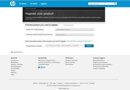
To experience quicker service and more efficient support, register the product at the HP Product Registration website.
Additional information
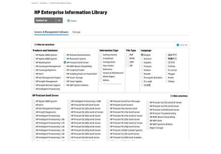
For more information, see the HP ProLiant MicroServer Gen8 documentation in the HP Enterprise Information Library.
For safety, environmental, and regulatory information, see Safety and Compliance Information for Server, Storage, Power, Networking, and Rack Products, available at the HP website.
HP is committed to providing documentation that meets your needs. To help us improve the documentation, send any errors, suggestions, or comments to Documentation Feedback. Include the document title and part number, version number, or the URL when submitting your feedback.
Part number: 718897-003
September 2015
Edition: 3