Example: Configuring DHCP client
Network configuration
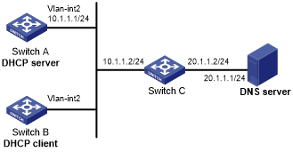
As shown in Figure 28, on a LAN, Switch B contacts the DHCP server through VLAN-interface 2 to obtain an IP address, a DNS server address, and static route information. The DHCP client's IP address resides on subnet 10.1.1.0/24. The DNS server address is 20.1.1.1. The next hop of the static route to subnet 20.1.1.0/24 is 10.1.1.2.
The DHCP server uses Option 121 to assign static route information to DHCP clients. Figure 27 shows the Option 121 format. The destination descriptor field contains the following parts: subnet mask length and destination network address, both in hexadecimal notation. In this example, the destination descriptor is 18 14 01 01 (the subnet mask length is 24 and the network address is 20.1.1.0 in dotted decimal notation). The next hop address is 0A 01 01 02 (10.1.1.2 in dotted decimal notation).
Figure 27: Option 121 format
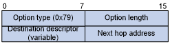
Figure 28: Network diagram
Procedure
Configure Switch A:
# Specify an IP address for VLAN-interface 2.
<SwitchA> system-view
[SwitchA] interface vlan-interface 2
[SwitchA-Vlan-interface2] ip address 10.1.1.1 24
[SwitchA-Vlan-interface2] quit
# Exclude an IP address from dynamic allocation.
[SwitchA] dhcp server forbidden-ip 10.1.1.2
# Configure DHCP address pool 0. Specify the subnet, lease duration, DNS server address, and a static route to subnet 20.1.1.0/24.
[SwitchA] dhcp server ip-pool 0
[SwitchA-dhcp-pool-0] network 10.1.1.0 mask 255.255.255.0
[SwitchA-dhcp-pool-0] expired day 10
[SwitchA-dhcp-pool-0] dns-list 20.1.1.1
[SwitchA-dhcp-pool-0] option 121 hex 18 14 01 01 0A 01 01 02
[SwitchA-dhcp-pool-0] quit
# Enable DHCP.
[SwitchA] dhcp enable
Configure Switch B:
# Configure VLAN-interface 2 to use DHCP for IP address acquisition.
<SwitchB> system-view
[SwitchB] interface vlan-interface 2
[SwitchB-Vlan-interface2] ip address dhcp-alloc
[SwitchB-Vlan-interface2] quit
Verifying the configuration
# Display the IP address and other network parameters assigned to Switch B.
[SwitchB-Vlan-interface2] display dhcp client verbose
Vlan-interface2 DHCP client information:
 Current state: BOUND
 Allocated IP: 10.1.1.3 255.255.255.0
 Allocated lease: 864000 seconds, T1: 331858 seconds, T2: 756000 seconds
 Lease from May 21 19:00:29 2012   to   May 31 19:00:29 2012
 DHCP server: 10.1.1.1
 Transaction ID: 0xcde72232
 Classless static routes:
   Destination: 20.1.1.0, Mask: 255.255.255.0, NextHop: 10.1.1.2
 DNS servers: 20.1.1.1
 Client ID type: acsii(type value=00)
 Client ID value: 000c.29d3.8659-Vlan2
 Client ID (with type) hex: 0030-3030-632e-3239-
                            6433-2e38-3635-392d-
                            4574-6830-2f30-2f32
 T1 will timeout in 3 days 19 hours 48 minutes 43 seconds
# Display the route information on Switch B. The output shows that a static route to subnet 20.1.1.0/24 is added to the routing table.
[SwitchB] display ip routing-table
Destinations : 11        Routes : 11
Destination/Mask    Proto  Pre  Cost         NextHop         Interface
10.1.1.0/24         Direct 0    0            10.1.1.3        Vlan2
10.1.1.3/32         Direct 0    0            127.0.0.1       InLoop0
20.1.1.0/24         Static 70   0            10.1.1.2        Vlan2
10.1.1.255/32       Direct 0    0            10.1.1.3        Vlan2
127.0.0.0/8         Direct 0    0            127.0.0.1       InLoop0
127.0.0.0/32        Direct 0    0            127.0.0.1       InLoop0
127.0.0.1/32        Direct 0    0            127.0.0.1       InLoop0
127.255.255.255/32  Direct 0    0            127.0.0.1       InLoop0
224.0.0.0/4         Direct 0    0            0.0.0.0         NULL0
224.0.0.0/24        Direct 0    0            0.0.0.0         NULL0
255.255.255.255/32  Direct 0    0            127.0.0.1       InLoop0