Example: Configuring common proxy ARP
Network configuration
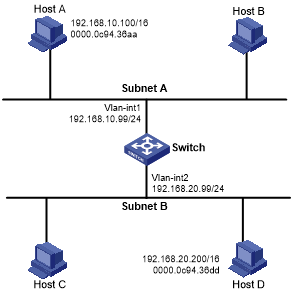
As shown in Figure 6, Host A and Host D have the same IP prefix and mask, but they are located on different subnets separated by the switch. Host A belongs to VLAN 1, and Host D belongs to VLAN 2. No default gateway is configured on Host A and Host D.
Configure common proxy ARP on the switch to enable communication between the two hosts.
Figure 6: Network diagram
Procedure
# Create VLAN 2.
<Switch> system-view
[Switch] vlan 2
[Switch-vlan2] quit
# Configure the IP address of VLAN-interface 1.
[Switch] interface vlan-interface 1
[Switch-Vlan-interface1] ip address 192.168.10.99 255.255.255.0
# Enable common proxy ARP on VLAN-interface 1.
[Switch-Vlan-interface1] proxy-arp enable
[Switch-Vlan-interface1] quit
# Configure the IP address of VLAN-interface 2.
[Switch] interface vlan-interface 2
[Switch-Vlan-interface2] ip address 192.168.20.99 255.255.255.0
# Enable common proxy ARP on VLAN-interface 2.
[Switch-Vlan-interface2] proxy-arp enable.
Verifying the configuration
# Verify that Host A and Host D can ping each other.