GRE application scenarios
The following shows typical GRE application scenarios:
Connecting networks running different protocols over a single backbone
Figure 135: Network diagram
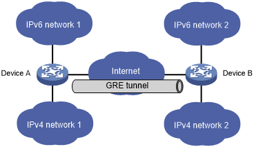
As shown in Figure 135, IPv6 network 1 and IPv6 network 2 are IPv6 networks, and IPv4 network 1 and IPv4 network 2 are IPv4 networks. Through the GRE tunnel between Device A and Device B, IPv6 network 1 can communicate with IPv6 network 2 and IPv4 network 1 can communicate with IPv4 network 2, without affecting each other.
Enlarging network scope
Figure 136: Network diagram
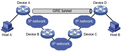
In an IP network, the maximum TTL value of a packet is 255. If two devices have more than 255 hops in between, they cannot communicate with each other. By using a GRE tunnel, you can hide some hops to enlarge the network scope. As shown in Figure 136, only the tunnel-end devices (Device A and Device D) of the GRE tunnel are counted in hop count calculation. Therefore, there are only three hops between Host A and Host B.
Constructing VPN
Figure 137: Network diagram
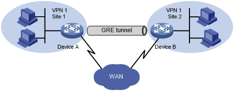
As shown in Figure 137, Site 1 and Site 2 both belong to VPN 1 and are located in different cities. Using a GRE tunnel can connect the two VPN sites across the WAN.
Operating with IPsec
Figure 138: Network diagram
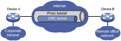
As shown in Figure 138, GRE can be used together with IPsec to form a GRE over IPsec tunnel. Packets (for example, routing protocol packets, voice data, and video data) are first encapsulated with GRE and then with IPsec. GRE over IPsec delivers the following benefits:
Improves transmission security.
Allows IPsec to protect not only unicast packets. GRE supports encapsulating multicast, broadcast, and non-IP packets. After GRE encapsulation, these packets become common unicast packets, which can be protected by IPsec.
Simplifies IPsec configuration. Packets are first encapsulated by GRE. You can define the packets to be protected by IPsec according to the GRE tunnel's source and destination addresses, without considering the source and destination addresses of the original packets.
GRE and IPsec can also form IPsec over GRE tunnels. As a best practice, use GRE over IPsec tunnels instead of IPsec over GRE tunnels.
For more information about IPsec, see Security Configuration Guide.