GRE tunnel operating principle
Figure 134: IPv6 networks interconnected through a GRE tunnel
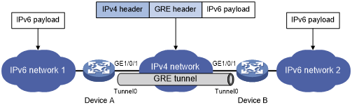
As shown in Figure 134, an IPv6 protocol packet traverses an IPv4 network through a GRE tunnel as follows:
After receiving an IPv6 packet from the interface connected to IPv6 network 1, Device A processes the packet as follows:
Looks up the routing table to identify the outgoing interface for the IPv6 packet.
Submits the IPv6 packet to the outgoing interface—the GRE tunnel interface Tunnel 0.
Upon receiving the packet, the tunnel interface encapsulates the packet with GRE and then with IPv4. In the IPv4 header:
The source address is the tunnel's source address (the IP address of interface GigabitEthernet 1/0/1 of Device A).
The destination address is the tunnel's destination address (the IP address of interface GigabitEthernet 1/0/1 of Device B).
Device A looks up the routing table according to the destination address in the IPv4 header, and forwards the IPv4 packet out of the physical interface (GigabitEthernet 1/0/1) of the GRE tunnel.
When the IPv4 arrives at the GRE tunnel destination Device B, Device B checks the destination address. Because the destination is Device B itself and the protocol number in the IP header is 47 (the protocol number for GRE), Device B submits the packet to GRE for de-encapsulation.
GRE first removes the IPv4 header, and then checks the GRE key, checksum, and packet sequence number. After GRE finishes the checking, it removes the GRE header, and submits the payload to the IPv6 protocol for forwarding.
![[NOTE: ]](images/note.png)
NOTE:
GRE encapsulation and de-encapsulation can decrease the forwarding efficiency of tunnel-end devices.