Configuration example
Network requirements
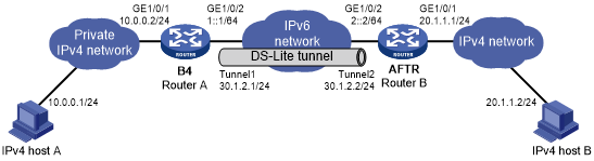
As shown in Figure 131, to enable hosts in the private IPv4 network to access the public IPv4 network over the IPv6 network, perform the following tasks:
Configure a DS-Lite tunnel between Router A and Router B.
Configure NAT on GigabitEthernet 1/0/1 on the AFTR.
Figure 131: Network diagram
Configuration procedure
Make sure Router A and Router B can reach each other through IPv6.
Configure Router A:
# Specify an IPv4 address for GigabitEthernet 1/0/1.
<RouterA> system-view
[RouterA] interface gigabitethernet 1/0/1
[RouterA-GigabitEthernet1/0/1] ip address 10.0.0.2 255.255.255.0
[RouterA-GigabitEthernet1/0/1] quit
# Specify an IPv6 address for GigabitEthernet 1/0/2, which is the physical interface of the tunnel.
[RouterA] interface gigabitethernet 1/0/2
[RouterA-GigabitEthernet1/0/2] ipv6 address 1::1 64
[RouterA-GigabitEthernet1/0/2] quit
# Create the IPv6 tunnel interface Tunnel 1.
[RouterA] interface tunnel 1 mode ipv6
# Specify an IPv4 address for the tunnel interface.
[RouterA-Tunnel1] ip address 30.1.2.1 255.255.255.0
# Specify the IP address of GigabitEthernet 1/0/2 as the source address for the tunnel interface.
[RouterA-Tunnel1] source 1::1
# Specify IP address of GigabitEthernet 1/0/2 on Router B as the destination address for the tunnel interface.
[RouterA-Tunnel1] destination 2::2
[RouterA-Tunnel1] quit
# Configure a static route to the public IPv4 network through the tunnel interface.
[RouterA] ip route-static 20.1.1.0 255.255.255.0 tunnel 1
Configure Router B:
# Specify an IPv4 address for GigabitEthernet 1/0/1.
<RouterB> system-view
[RouterB] interface gigabitethernet 1/0/1
[RouterB-GigabitEthernet1/0/1] ip address 20.1.1.1 24
[RouterB-GigabitEthernet1/0/1] quit
# Specify an IPv6 address for GigabitEthernet 1/0/2, which is the physical interface of the tunnel.
[RouterB] interface gigabitethernet 1/0/2
[RouterB-GigabitEthernet1/0/2] ipv6 address 2::2 64
[RouterB-GigabitEthernet1/0/2] quit
# Create the DS-Lite tunnel interface Tunnel 2.
[RouterB] interface tunnel 2 mode ds-lite-aftr
# Configure an IPv4 address for the tunnel interface.
[RouterB-Tunnel2] ip address 30.1.2.2 255.255.255.0
# Specify GigabitEthernet 1/0/2 as the source interface of the tunnel interface.
[RouterB-Tunnel2] source gigabitethernet 1/0/2
[RouterB-Tunnel2] quit
# Enable DS-Lite tunneling on GigabitEthernet 1/0/1.
[RouterB] interface gigabitethernet 1/0/1
[RouterB-GigabitEthernet1/0/1] ds-lite enable
# Enable NAT on GigabitEthernet 1/0/1 and use the IP address of GigabitEthernet 1/0/1 as the translated address.
[RouterB-GigabitEthernet1/0/1] nat outbound
[RouterB-GigabitEthernet1/0/1] quit
On host A, specify the IP address for the host as 10.0.0.1 and configure a static route to 20.1.1.0/24 with next hop 10.0.0.2. (Details not shown.)
On host B, specify the IP address for the host as 20.1.1.2. (Details not shown.)
Verifying the configuration
# Use the display interface tunnel command to display the status of the tunnel interfaces on Router A and Router B. Verify that the tunnel interfaces are up. (Details not shown.)
# Verify that host A can ping host B.
C:\> ping 20.1.1.2
Pinging 20.1.1.2 with 32 bytes of data:
Reply from 20.1.1.2: bytes=32 time=51ms TTL=255
Reply from 20.1.1.2: bytes=32 time=44ms TTL=255
Reply from 20.1.1.2: bytes=32 time=1ms TTL=255
Reply from 20.1.1.2: bytes=32 time=1ms TTL=255
Ping statistics for 20.1.1.2:
    Packets: Sent = 4, Received = 4, Lost = 0 (0% loss),
Approximate round trip times in milli-seconds:
    Minimum = 1ms, Maximum = 51ms, Average = 24ms