Configuration example
Network requirements
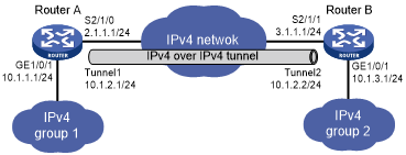
As shown in Figure 129, the two subnets IPv4 group 1 and IPv4 group 2 use private IPv4 addresses. Configure an IPv4 over IPv4 tunnel between Router A and Router B to make the two subnets reachable to each other.
Figure 129: Network diagram
Configuration procedure
Make sure Router A and Router B can reach each other through IPv4.
Configure Router A:
# Specify an IPv4 address for GigabitEthernet 1/0/1.
<RouterA> system-view
[RouterA] interface gigabitethernet 1/0/1
[RouterA-GigabitEthernet1/0/1] ip address 10.1.1.1 255.255.255.0
[RouterA-GigabitEthernet1/0/1] quit
# Specify an IPv4 address for Serial 2/1/0, which is the physical interface of the tunnel.
[RouterA] interface serial 2/1/0
[RouterA-Serial2/1/0] ip address 2.1.1.1 255.255.255.0
[RouterA-Serial2/1/0] quit
# Create the IPv4 over IPv4 tunnel interface Tunnel 1.
[RouterA] interface tunnel 1 mode ipv4-ipv4
# Specify an IPv4 address for the tunnel interface.
[RouterA-Tunnel1] ip address 10.1.2.1 255.255.255.0
# Specify the IP address of Serial 2/1/0 as the source address for the tunnel interface.
[RouterA-Tunnel1] source 2.1.1.1
# Specify the IP address of Serial 2/1/1 on Router B as the destination address for the tunnel interface.
[RouterA-Tunnel1] destination 3.1.1.1
[RouterA-Tunnel1] quit
# Configure a static route destined for IPv4 group 2 through the tunnel interface.
[RouterA] ip route-static 10.1.3.0 255.255.255.0 tunnel 1
Configure Router B:
# Specify an IPv4 address for GigabitEthernet 1/0/1.
<RouterB> system-view
[RouterB] interface gigabitethernet 1/0/1
[RouterB-GigabitEthernet1/0/1] ip address 10.1.3.1 255.255.255.0
[RouterB-GigabitEthernet1/0/1] quit
# Specify an IPv4 address for Serial 2/1/1, which is the physical interface of the tunnel.
[RouterB] interface serial 2/1/1
[RouterB-Serial2/1/1] ip address 3.1.1.1 255.255.255.0
[RouterB-Serial2/1/1] quit
# Create the IPv4 over IPv4 tunnel interface Tunnel 2.
[RouterB] interface tunnel 2 mode ipv4-ipv4
# Specify an IPv4 address for the tunnel interface.
[RouterB-Tunnel2] ip address 10.1.2.2 255.255.255.0
# Specify the IP address of Serial 2/1/1 as the source address for the tunnel interface.
[RouterB-Tunnel2] source 3.1.1.1
# Specify the IP address of Serial 2/1/0 on Router A as a destination address for the tunnel interface.
[RouterB-Tunnel2] destination 2.1.1.1
[RouterB-Tunnel2] quit
# Configure a static route destined for IPv4 group 1 through the tunnel interface.
[RouterB] ip route-static 10.1.1.0 255.255.255.0 tunnel 2
Verifying the configuration
# Use the display interface tunnel command to display the status of the tunnel interfaces on Router A and Router B. Verify that the tunnel interfaces are up. (Details not shown.)
# Verify that Router A and Router B can ping the IPv4 address of the peer interface GigabitEthernet 1/0/1. This example uses Router A.
[RouterA] ping -a 10.1.1.1 10.1.3.1
Ping 10.1.3.1 (10.1.3.1) from 10.1.1.1: 56 data bytes, press CTRL_C to break
56 bytes from 10.1.3.1: icmp_seq=0 ttl=255 time=2.000 ms
56 bytes from 10.1.3.1: icmp_seq=1 ttl=255 time=1.000 ms
56 bytes from 10.1.3.1: icmp_seq=2 ttl=255 time=0.000 ms
56 bytes from 10.1.3.1: icmp_seq=3 ttl=255 time=1.000 ms
56 bytes from 10.1.3.1: icmp_seq=4 ttl=255 time=1.000 ms

--- Ping statistics for 10.1.3.1 ---
5 packet(s) transmitted, 5 packet(s) received, 0.0% packet loss
round-trip min/avg/max/std-dev = 0.000/1.000/2.000/0.632 ms