E&M interface configuration example
Network requirements
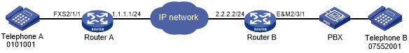
As shown in Figure 11, Router A and Router B are connected through an IP network and can reach each other.
Configure the two routers to enable Telephone A and Telephone B to establish calls.
Figure 11: Network diagram
Configuration procedure
Configure Router A:
# Configure the called number as 07552001 for VoIP entity 0755, and configure the destination IP address as 2.2.2.2.
<RouterA> system-view
[RouterA] voice-setup
[RouterA-voice] dial-program
[RouterA-voice-dial] entity 0755 voip
[RouterA-voice-dial-entity755] match-template 07552001
[RouterA-voice-dial-entity755] address sip ip 2.2.2.2
[RouterA-voice-dial-entity755] quit
# Configure the local number as 0101001 for POTS entity 1001, and bind FXS interface line 2/1/1 to the POTS entity.
[RouterA-voice-dial] entity 1001 pots
[RouterA-voice-dial-entity1001] match-template 0101001
[RouterA-voice-dial-entity1001] line 2/1/1
Configure Router B:
# Configure the called number as 0101001 for VoIP entity 010, and configure the destination IP address as 1.1.1.1.
<RouterB> system-view
[RouterB] voice-setup
[RouterB-voice] dial-program
[RouterB-voice-dial] entity 010 voip
[RouterB-voice-dial-entity10] match-template 0101001
[RouterB-voice-dial-entity10] address sip ip 1.1.1.1
[RouterB-voice-dial-entity10] quit
# Configure the local number as 07552001 for POTS entity 2001, and bind E&M interface line 2/3/1 to the POTS entity.
[RouterB-voice-dial] entity 2001 pots
[RouterB-voice-dial-entity2001] match-template 07552001
[RouterB-voice-dial-entity2001] send-number all
[RouterB-voice-dial-entity2001] line 2/3/1
[RouterB-voice-dial-entity2001] return
# Enter the view of E&M interface 5/0. The E&M interface must have the same configuration as the connected PBX.
<RouterB> system-view
[RouterB] subscriber-line 2/3/1
# Configure the wink start mode.
[RouterB-subscriber-line2/3/1] signal wink
# Configure the 4-wire cable type (optional, because the default is the 4-wire cable type).
[RouterB-subscriber-line2/3/1] cable 4-wire
# Configure the signal type as 5 (optional, because the default is 5).
[RouterB-subscriber-line2/3/1] type 5
Verifying the configuration
# Dial 07552001 (Telephone B) from Telephone A to verify that Telephone A can establish calls with Telephone B.
# Dial 0101001 (Telephone A) from Telephone B to verify that Telephone B can establish calls with Telephone A.