PPPoE server RADIUS-based IP address assignment configuration example
Network requirements
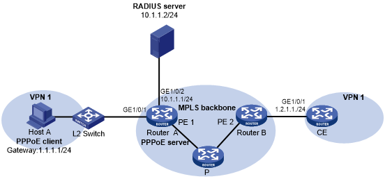
As shown in Figure 15, configure the PPPoE server to meet the following requirements:
The PPPoE server uses the RADIUS server to perform authentication, authorization, and accounting for access users
The RADIUS server assigns access users a PPP address pool named pool1 and a VPN instance named vpn1.
Users in vpn1 obtain IP addresses from PPP address pool pool1.
Figure 15: Network diagram
Configuration procedure
Configure the MPLS L3VPN feature.
For the two ends of VPN 1 to communicate with each other, specify the same route target attributes on the two PEs (Router A and Router B). This example describes only the authentication-related configuration on the PE that is connected to the PPPoE client. For information about configuring MPLS L3VPN, see MPLS Configuration Guide.
Configure the RADIUS server:
This example uses Free RADIUS that runs in the Linux operating system.
# Add the following text to the client.conf file to configure RADIUS client information.
client 10.1.1.1/24 {
secret = radius
shortname = sr88
}
Where, secret represents the shared key for authentication, authorization, and accounting.
# Add the following text to the users.conf file to configure legal user information.
user1  Auth-Type == CHAP,User-Password := pass1
          Service-Type = Framed-User,
          Framed-Protocol = PPP,
          Framed-IPv6-Pool = "pool1",
          HPE-VPN-Instance = "vpn1",
Configure Router A:
Configure the PPPoE server:
# Configure Virtual-Template 1 to use CHAP for authentication and use ISP domain dm1 as the authentication domain.
<RouterA> system-view
[RouterA] interface virtual-template 1
[RouterA-Virtual-Template1] ppp authentication-mode chap domain dm1
[RouterA-Virtual-Template1] quit
# Create a PPP address pool that contains nine assignable IP addresses.
[RouterA] ip pool pool1 1.1.1.2 1.1.1.10 group 1
# Specify gateway address 1.1.1.1 and VPN instance vpn1 for pool1.
[RouterA] ip pool pool1 gateway 1.1.1.1 vpn-instance vpn1
# Configure a PPP address pool route for pool1.
[RouterA] ppp ip-pool route 1.1.1.1 24 vpn-instance vpn1
# Enable the PPPoE server on GigabitEthernet 1/0/1, and bind the interface to Virtual-Template 1.
[RouterA] interface gigabitethernet 1/0/1
[RouterA-GigabitEthernet1/0/1] pppoe-server bind virtual-template 1
[RouterA-GigabitEthernet1/0/1] quit
Configure a RADIUS scheme:
# Create a RADIUS scheme named rs1, and enter its view.
[RouterA] radius scheme rs1
# Specify the primary authentication server and the primary accounting server.
[RouterA-radius-rs1] primary authentication 10.1.1.2
[RouterA-radius-rs1] primary accounting 10.1.1.2
# Set the shared key for secure communication with the server to radius in plain text.
[RouterA-radius-rs1] key authentication simple radius
[RouterA-radius-rs1] key accounting simple radius
# Exclude domain names in the usernames sent to the RADIUS server.
[RouterA-radius-rs1] user-name-format without-domain
[RouterA-radius-rs1] quit
Configure an authentication domain:
# Create an ISP domain named dm1.
[RouterA] domain dm1
# In ISP domain dm1, perform RADIUS authentication, authorization, and accounting for users based on scheme rs1.
[RouterA-isp-dm1] authentication ppp radius-scheme rs1
[RouterA-isp-dm1] authorization ppp radius-scheme rs1
[RouterA-isp-dm1] accounting ppp radius-scheme rs1
[RouterA-isp-dm1] quit
Verifying the configuration
# Verify that Host A can successfully ping CE. (Details not shown.)
# Verify that the PPPoE client has obtained an IP address from pool1.
[RouterA] display ip pool pool1
Group name: 1
  Pool name       Start IP address    End IP address     Free    In use
  pool1           1.1.1.2             1.1.1.10           8       1
In use IP addresses:
  IP address      Interface
1.1.1.2 VA0