Configuring the basic X.25 switching functionality
A packet network consists of many interconnecting nodes based on a specific topology. A packet is sent from source to destination through a large number of nodes, of which each node needs to have packet switching capability.
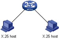
Simply speaking, X.25 packet switching means, after receiving a packet from an X.25 port or Annex G DLCI, a switch will select a certain X.25 port or Annex G DLCI to send the packet according to the related destination information contained in the packet. Introducing X.25 switching enables the system to implement the packet switching function at the packet layer. The device can act as a packet switch.
Figure 126: X.25 switching
To configure the basic X.25 switching functionality:
Step | Command | Remarks |
|---|---|---|
1. Enter system view. | system-view | N/A |
2. Enable X.25 switching. | x25 switching | Disabled by default. |
3. Add a switching route |
| N/A |
Enabling/Disabling X.25 switching only affects call establishment, and does not affect the established links.
The switching routes can be configured only after X.25 switching is enabled. If you disable the switching (by using the undo x25 switching command) after configuring some switching routes, then
All static SVC routes will be invisible in the related display command, and PVC routes will be visible in the related display command.
If you execute the x25 switching command again without restart, SVC routes will be restored and visible on using the display command.
If you execute the save command and restart, all SVC and PVC routes will be lost.
Because the default two-way channel range (LTC=1, HTC=1024) does not support PVC configuration, specify a virtual circuit range by using the x25 vc-range command to create a PVC.