Modem management configuration example
Network requirements
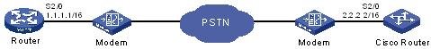
A device is connected to a Cisco router through its Serial 2/0 interface and two modems. A connection between the two devices is established through DCC dialup when data is to be transmitted between them. For more information about DCC dialup, see "Configuring DCC."
Figure 62: Network diagram
Configuration procedure
Configure Router:
# Create dialer access group 1 and configure it to permit all IP packets.
<Router> system-view
[Router] dialer-rule 1 ip permit
# Configure interface Serial 2/0 to operate in asynchronous mode and then configure it to operate in protocol mode.
[Router] interface serial 2/0
[Router-Serial2/0] physical-mode async
[Router-Serial2/0] async mode protocol
# Configure the link layer protocol of interface Serial 2/0 as PPP.
[Router-Serial2/0] link-protocol ppp
# Configure an IP address for interface Serial 2/0.
[Router-Serial2/0] ip address 1.1.1.1 255.255.0.0
# Enable C-DCC on interface Serial 2/0.
[Router-Serial2/0] dialer enable-circular
# Assign interface Serial 2/0 to dialer access group 1.
[Router-Serial2/0] dialer-group 1
# Set the link holddown timer to 5 seconds.
[Router-Serial2/0] dialer timer enable 5
# Configure the dial number for placing calls to a single remote end as 666666.
[Router-Serial2/0] dialer number 666666
[Router-Serial2/0] quit
# Enables both modem call-in and modem call-out on user-interface TTY 1.
[Router] user-interface tty 1
[Router-ui-tty1] modem both
For information about DCC commands, see HPE FlexNetwork MSR Router Series Comware 5 Layer 2—WAN Command Reference.
Configure the Cisco router:
For more information, see Cisco documentation.