Network requirements
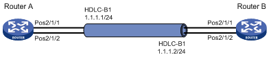
As shown in Figure 37, to increase bandwidth and enhance connection reliability between Router A and Router B, create an HDLC link bundle.
Figure 37: Network diagram
Configuration procedure
Configuring Router A
# Create HDLC link bundle interface 1 and assign an IP address to it.
<RouterA> system-view
[RouterA] interface hdlc-bundle 1
[RouterA-HDLC-bundle1] ip address 1.1.1.1 24
[RouterA-HDLC-bundle1] quit
# Assign POS interfaces POS 2/1/1 to HDLC link bundle 1, and configure the interface to use the master clock mode.
[RouterA] interface pos 2/1/1
[RouterA-Pos2/1/1] clock master
[RouterA-Pos2/1/1] link-protocol hdlc
[RouterA-Pos2/1/1] bundle id 1
[RouterA-Pos2/1/1] quit
# Assign POS interfaces POS 2/1/2 to HDLC link bundle 1, and configure the interface to use the master clock mode.
[RouterA] interface pos 2/1/2
[RouterA-Pos2/1/2] clock master
[RouterA-Pos2/1/2] link-protocol hdlc
[RouterA-Pos2/1/2] bundle id 1
[RouterA-Pos2/1/2] quit
Configuring Router B
# Create HDLC link bundle interface 1 and assign an IP address to it.
<RouterB> system-view
[RouterB] interface hdlc-bundle 1
[RouterB-HDLC-bundle1] ip address 1.1.1.2 24
[RouterB-HDLC-bundle1] quit
# Assign POS interfaces POS 2/1/1 to HDLC link bundle 1.
[RouterB] interface pos 2/1/1
[RouterB-Pos2/1/1] link-protocol hdlc
[RouterB-Pos2/1/1] bundle id 1
[RouterB-Pos2/1/1] quit
# Assign POS interfaces POS 2/1/2 to HDLC link bundle 1.
[RouterB] interface pos 2/1/2
[RouterB-Pos2/1/2] link-protocol hdlc
[RouterB-Pos2/1/2] bundle id 1
[RouterB-Pos2/1/2] quit