Configuration example for LAC-auto-initiated L2TP tunnel
Network requirements
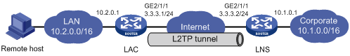
As shown in Figure 35, configure the LAC to establish an L2TP tunnel with the LNS in LAC-auto-initiated mode. When the PPP user initiates a connection, it uses the established tunnel to access the corporate network.
Figure 35: Network diagram
Configuration procedure
Configure the LNS:
# Configure IP addresses for the interfaces. (Details not shown.)
# Create a local user named vpdnuser, set the password, and enable the PPP service.
<LNS> system-view
[LNS] local-user vpdnuser class network
[LNS-luser-network-vpdnuser] password simple Hello
[LNS-luser-network-vpdnuser] service-type ppp
[LNS-luser-network-vpdnuser] quit
# Create a PPP address pool.
[LNS] ip pool aaa 192.168.0.10 192.168.0.20
[LNS] ip pool aaa gateway 192.168.0.1
# Create Virtual-Template 1, specify its PPP authentication mode as PAP, and use address pool aaa to assign IP addresses to the PPP users.
[LNS] interface virtual-template 1
[LNS-virtual-template1] ppp authentication-mode pap
[LNS-virtual-template1] remote address pool aaa
[LNS-virtual-template1] quit
# Configure local authentication for PPP users in ISP domain system.
[LNS] domain system
[LNS-isp-system] authentication ppp local
[LNS-isp-system] quit
# Enable L2TP, and create L2TP group 1 in LNS mode.
[LNS] l2tp enable
[LNS] l2tp-group 1 mode lns
# Configure the local tunnel name as LNS, and specify Virtual-Template 1 for receiving tunneling requests from an LAC.
[LNS-l2tp1] tunnel name LNS
[LNS-l2tp1] allow l2tp virtual-template 1 remote LAC
# Enable tunnel authentication, and configure the authentication key as aabbcc.
[LNS-l2tp1] tunnel authentication
[LNS-l2tp1] tunnel password simple aabbcc
[LNS-l2tp1] quit
# Configure a static route so that packets destined for the PPP user will be forwarded through the L2TP tunnel.
[LNS] ip route-static 10.2.0.0 16 192.168.0.10
Configure the LAC:
# Configure IP addresses for the interfaces. (Details not shown.)
# Enable L2TP.
<LAC> system-view
[LAC] l2tp enable
# Create L2TP group 1 in LAC mode.
[LAC] l2tp-group 1 mode lac
# Configure the local tunnel name as LAC, and specify the IP address of the tunnel peer (LNS).
[LAC-l2tp1] tunnel name LAC
[LAC-l2tp1] lns-ip 3.3.3.2
# Enable tunnel authentication, and configure the authentication key as aabbcc.
[LAC-l2tp1] tunnel authentication
[LAC-l2tp1] tunnel password simple aabbcc
[LAC-l2tp1] quit
# Create Virtual-PPP 1. Configure its username and password as vpdnuser and Hello and PPP authentication as PAP.
[LAC] interface virtual-ppp 1
[LAC-Virtual-PPP1] ip address ppp-negotiate
[LAC-Virtual-PPP1] ppp pap local-user vpdnuser password simple Hello
[LAC-Virtual-PPP1] quit
# Configure a static route so that packets destined for the corporate network will be forwarded through the L2TP tunnel.
[LAC] ip route-static 10.1.0.0 16 virtual-ppp 1
# Trigger the LAC to establish an L2TP tunnel with the LNS.
[LAC] interface virtual-ppp 1
[LAC-Virtual-PPP1] l2tp-auto-client l2tp-group 1
On the remote host, configure the LAC as the gateway.
Verifying the configuration
# On the LNS, use the display l2tp session command to display the established L2TP session.
[LNS] display l2tp session
LocalSID      RemoteSID      LocalTID      State
21409         3395           4501          Established
# On the LNS, use the display l2tp tunnel command to display the established L2TP tunnel.
[LNS] display l2tp tunnel
LocalTID RemoteTID State         Sessions RemoteAddress    RemotePort RemoteName
4501     524       Established   1        3.3.3.1          1701       LAC
# On the LNS, verify that you can ping 10.2.0.1, a private network address on the LAC side. This indicates that hosts on 10.2.0.0/16 and those on 10.1.0.0/16 can communicate with each other through the L2TP tunnel.
[LNS] ping -a 10.1.0.1 10.2.0.1
Ping 10.2.0.1 (10.2.0.1): 56 data bytes, press CTRL_C to break
56 bytes from 10.2.0.1: icmp_seq=0 ttl=128 time=1.000 ms
56 bytes from 10.2.0.1: icmp_seq=1 ttl=128 time=1.000 ms
56 bytes from 10.2.0.1: icmp_seq=2 ttl=128 time=1.000 ms
56 bytes from 10.2.0.1: icmp_seq=3 ttl=128 time=1.000 ms
56 bytes from 10.2.0.1: icmp_seq=4 ttl=128 time=1.000 ms

--- Ping statistics for 10.2.0.1 ---
5 packet(s) transmitted, 5 packet(s) received, 0.0% packet loss
round-trip min/avg/max/std-dev = 1.000/1.000/1.000/0.000 ms