One-way PAP authentication configuration example
Network requirements
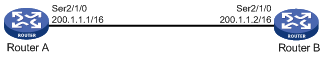
As shown in Figure 3, configure Router A to authenticate Router B by using PAP, but Router B not to authenticate Router A.
Figure 3: Network diagram
Configuration procedure
Configure Router A:
# Create a user account for Router B.
<RouterA> system-view
[RouterA] local-user userb class network
# Set a password for the user account.
[RouterA-luser-network-userb] password simple passb
# Set the service type of the user account to PPP.
[RouterA-luser-network-userb] service-type ppp
[RouterA-luser-network-userb] quit
# Enable PPP encapsulation on Serial 2/1/0. By default, an interface uses PPP encapsulation.
[RouterA] interface serial 2/1/0
[RouterA-Serial2/1/0] link-protocol ppp
# Set the authentication mode to PAP.
[RouterA-Serial2/1/0] ppp authentication-mode pap domain system
# Assign an IP address to Serial 2/1/0.
[RouterA-Serial2/1/0] ip address 200.1.1.1 16
[RouterA-Serial2/1/0] quit
# Configure local authentication for the PPP users in the default ISP domain (system).
[RouterA] domain system
[RouterA-isp-system] authentication ppp local
Configure Router B:
# Enable PPP encapsulation on Serial 2/1/0. By default, an interface uses PPP encapsulation.
<RouterB> system-view
[RouterB] interface serial 2/1/0
[RouterB-Serial2/1/0] link-protocol ppp
# Configure the PAP username and password sent from Router B to Router A when Router B is authenticated by Router A using PAP.
[RouterB-Serial2/1/0] ppp pap local-user userb password simple passb
# Assign an IP address to Serial 2/1/0 of Router B.
[RouterB-Serial2/1/0] ip address 200.1.1.2 16
Verifying the configuration
# Use the display interface serial command to display information about Serial 2/1/0 of Router B.
[RouterB-Serial2/1/0] display interface serial 2/1/0
Serial2/1/0
Current state: UP
Line protocol state: UP
Description: Serial2/1/0 Interface
Bandwidth: 64kbps
Maximum Transmit Unit: 1500
Internet Address: 200.1.1.2/16 Primary
Link layer protocol: PPP
LCP: opened, IPCP: opened
...
The output shows that:
The physical layer status and link layer status of the interface are both up.
The states of LCP and IPCP are both Opened, indicating that PPP negotiation has succeeded.
# Verify that Router A and Router B can ping each other.
[RouterB-Serial2/1/0] ping 200.1.1.1
5 packet(s) transmitted, 5 packet(s) received, 0.0% packet loss Ping 200.1.1.1 (200.1.1.1): 56 data bytes, press CTRL_C to break
56 bytes from 200.1.1.1: icmp_seq=0 ttl=128 time=3.197 ms
56 bytes from 200.1.1.1: icmp_seq=1 ttl=128 time=2.594 ms
56 bytes from 200.1.1.1: icmp_seq=2 ttl=128 time=2.739 ms
56 bytes from 200.1.1.1: icmp_seq=3 ttl=128 time=1.738 ms
56 bytes from 200.1.1.1: icmp_seq=4 ttl=128 time=1.744 ms

--- Ping statistics for 200.1.1.1 ---
5 packet(s) transmitted, 5 packet(s) received, 0.0% packet loss
round-trip min/avg/max/std-dev = 1.738/2.402/3.197/0.576 ms