Aruba 8400 Switch Series member, slot, and port notation
The software notation for describing member, slot, and port information depends on the switch hardware.
The physical interfaces on the Aruba 8400 Switch Series use the format:
member/slot/port- member
Specifies the chassis number. In this release of the software, the value of member is always
1.- slot
Specifies physical location in the switch chassis.
- port
Specifies the physical port on the module.
The slot numbers are unique to each type of component—in contrast to being unique within a chassis.
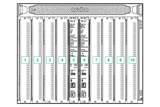
Line Modules and Management Modules
Line modules are on the front of the switch in slots 1/1 through 1/4 and 1/7 through 1/10.
The number of ports depend on the line module. Line module ports are labeled in software as port or interface, depending on the context.
For example,
interface 1/1/1 is the logical interface associated with the physical interface member 1, slot 1, port 1.
Management modules are on the front of the switch in slots 1/5 and 1/6.
Power supplies
Power supplies are on the front of the switch behind the bezel above the line modules and management modules. Power supplies are labeled in software as Member/PSU: 1/1 through 1/4.
Fan trays
Fan trays are on the rear of the switch and are labeled in software as Member/Tray: 1/1 through 1/3.
Fans
Fans are on the rear of the switch in fan trays and are labeled in software as Member/Tray/Fan:
1/1/1 through 1/1/6
1/2/1 through 1/2/6
1/3/1 through 1/3/6
Fabric modules
Fabric modules are on the rear of the switch, behind the fan trays, in slots 1/1 through 1/3.
Rear display module
The rear display module is on the rear of the switch and is not labeled with a member or slot number.